By-pass valve mechanism and method of use hereof

a technology of bypass valve and valve body, which is applied in the direction of fluid removal, sealing/packing, borehole/well accessories, etc., can solve the problems of inability to control the pressure surge, tubing may be intentionally blocked, and the effect of energizing the sealing elemen

Inactive Publication Date: 2004-08-19
SCHLUMBERGER TECH CORP
View PDF4 Cites 62 Cited by
  • Summary
  • Abstract
  • Description
  • Claims
  • Application Information

AI Technical Summary

Problems solved by technology

Bull-heading, i.e., displacing well fluid into a reservoir, is often unacceptable as it can lead to well control problems, cause formation damage and can induce pressure surges that are intolerable by some flow or pressure sensitive devices.
However, in some applications the tubing may be intentionally blocked, or the device may utilize cup type or flow sensitive sealing elements which may prevent displaced fluid flow externally of the tool.
Tools using cup type self energizing sealing elements are very sensitive to differential pressure or flow and may become prematurely energized if the tool run in speed exceeds t

Method used


Image

  • By-pass valve mechanism and method of use hereof
  • By-pass valve mechanism and method of use hereof
  • By-pass valve mechanism and method of use hereof

Examples


Embodiment Construction

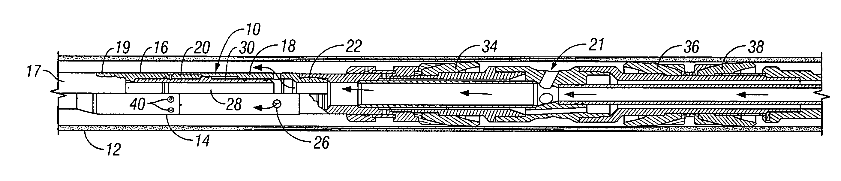
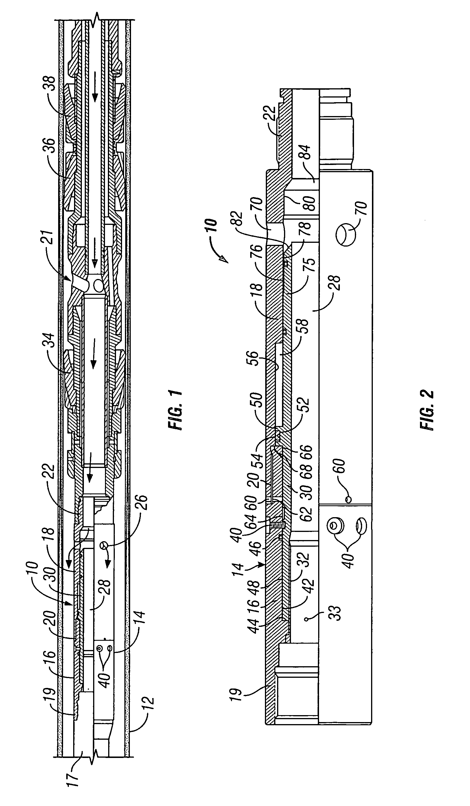
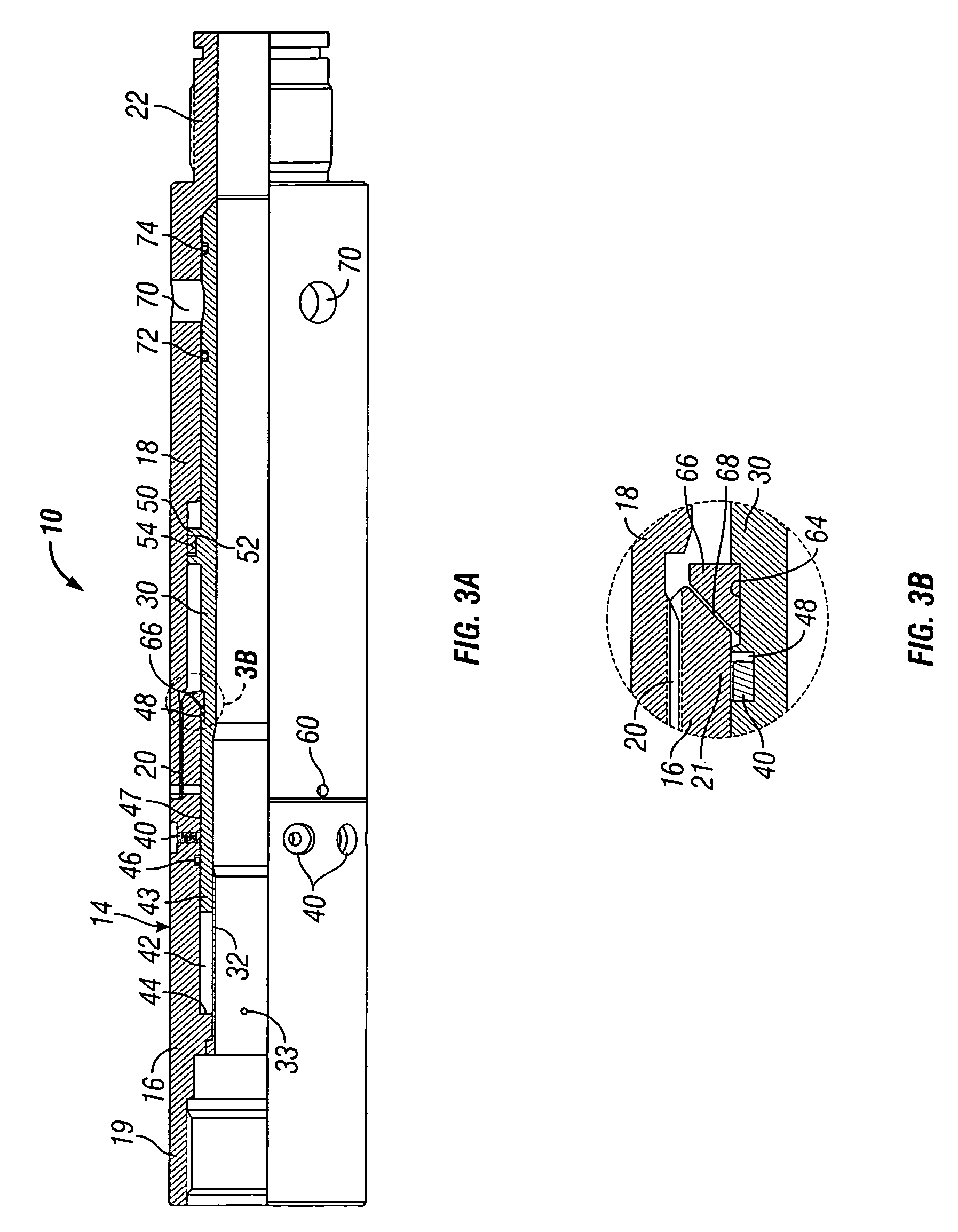
[0027] Referring now to the drawings and first to FIG. 1, a by-pass valve mechanism or assembly embodying the principles of the present invention is shown generally at 10 and is shown to be located within a well casing 12, such as during its conveyance downwardly through the well casing to a depth or location of interest. The by-pass valve, as illustrated in FIG. 1, is composed of a fixed outer ported housing shown generally at 14 and having upper and lower housing sections 16 and 18, being connected in assembly by an intermediate connection 20. A tubing connector 17 of a conveyance and fluid supplying tubing string is received by a connector 19 defined by the upper end of the upper housing section 14, thus providing for connection of the by-pass valve assembly with the tubing string for fluid supply to a well service tool shown generally at 21 and for conveyance of the well service tool within the well casing.

[0028] The lower housing section 18 defines a tool connection 22 to provi...


PUM


Abstract

A by-pass valve mechanism for a well treatment tool having at least one flow sensitive element, permitting by-pass of well fluid past the flow sensitive element of the well treatment tool during conveyance of the well treatment tool to treatment depth within a well. A valve housing adapted for connection with a well tool defines an internal flow passage and has at least one by-pass port communicating well fluid between the flow passage of the service tool and the annulus between the well casing and the service tool. A sliding sleeve valve element is normally secured at its open position by shear elements permitting flow of well fluid through the and is moveable between an open position diverting fluid flow from within the service tool to the annulus and a closed position blocking the flow of well fluid through the by-pass port. The sleeve valve element is released and automatically closed by predetermined hydrostatic tubing or casing pressure or pump pressure. The by-pass valve mechanism may have a test pressure control system permitting pressure testing of a well without causing release and closure of the sleeve valve.

Description

RELATED PATENT APPLICATION[0001] Applicants hereby claim the benefit of U.S. Provisional Application Serial No. 60 / 448,334 filed on Feb. 19, 2003 and entitled "By-pass Valve & Method", which provisional application is incorporated herein by reference for all purposes.[0002] 1. Field of the Invention[0003] The present invention relates generally to by-pass valves to provide for by-pass of fluid within a well casing past a well tool having packer elements as the tool is being run into a well to provide a well servicing activity. More particularly, the present invention concerns a by-pass valve having a unique closable sleeve valve that provides an alternative flow path for displaced well fluids to travel across flow sensitive or restrictive bottom hole assemblies.[0004] 2. Description of the Prior Art[0005] The process of conveying tools into well bores filled with fluid generally involves a displacement of fluids. During conveyance of a well tool within a well, fluids must be transfe...

Claims


Application Information

Patent Timeline
IPC IPC(8): E21B33/129
CPCE21B33/1294
Inventor BISSONNETTE, H. STEVENRYDER, KEITH A.MCKEE, L. MICHAEL
Owner SCHLUMBERGER TECH CORP
Why Eureka
Try Eureka