Method of working a concrete surface

a concrete surface and surface technology, applied in the direction of hydraulic mining, dislodge machines, surface mining, etc., can solve the problem of high maintenance costs

Inactive Publication Date: 2005-04-12
CONJET
View PDF10 Cites 33 Cited by
  • Summary
  • Abstract
  • Description
  • Claims
  • Application Information

AI Technical Summary

Benefits of technology

It is advantageous to step forward the holder (30) while it is being swung to its new attacking angle. It is then also advantageous to adapt the swing velocity of the holder to its linear movement so that the water jet makes a cut (34) in the direction of stepping. It is particularly advantageous to begin and end the stepping and the swinging of the holder simultaneously.

Problems solved by technology

The maintenance costs will be high if the salt already has had an effect on the reinforcement.

Method used


Image

  • Method of working a concrete surface
  • Method of working a concrete surface
  • Method of working a concrete surface

Examples


Embodiment Construction

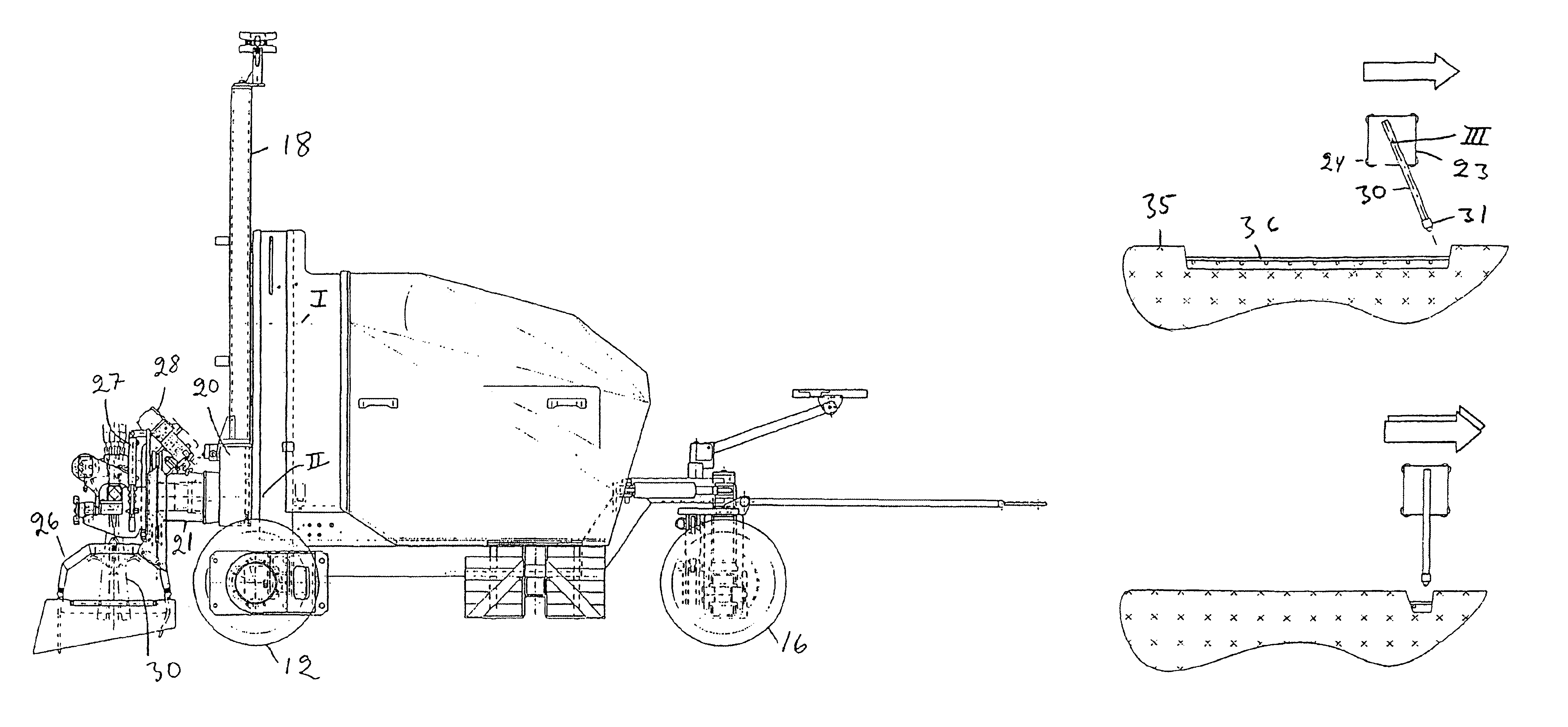
It is an object of the invention to provide a more uniform cutting at the edges than can be reached by prior art technique. To this end, when the water jet reaches its end position, the holder is swung to give the nozzle its attacking angle in the subsequent step while the carrier continues its movement towards its position of turning. The invention has been given the characteristics defined in the claims.

It is advantageous to step forward the holder (30) while it is being swung to its new attacking angle. It is then also advantageous to adapt the swing velocity of the holder to its linear movement so that the water jet makes a cut (34) in the direction of stepping. It is particularly advantageous to begin and end the stepping and the swinging of the holder simultaneously.

BRIEF DESCRIPTION OF THE DRAWING

FIG. 1 is a side view of a machine by which the method according to the invention can be carried out.

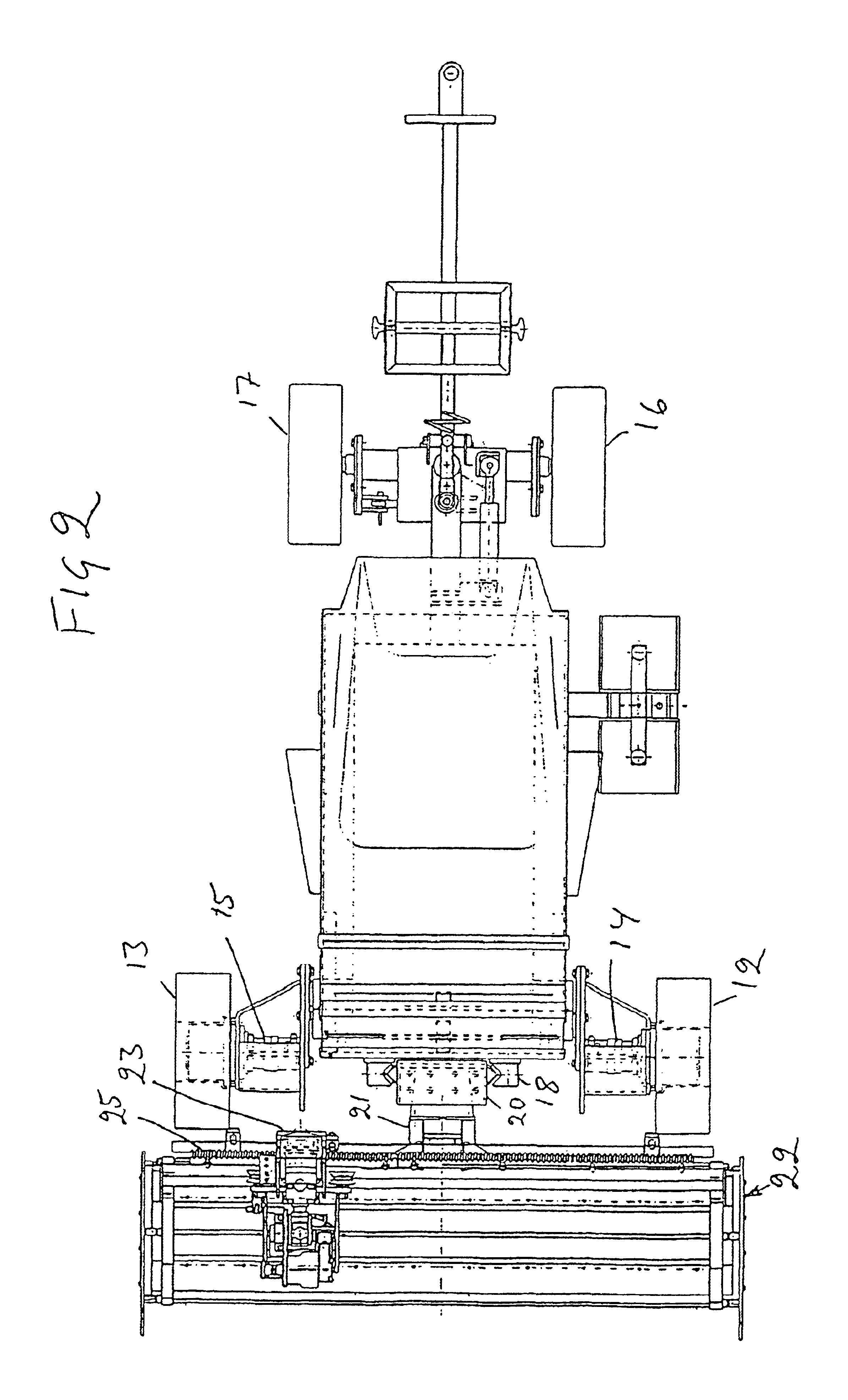
FIG. 2 is a top elevation view of the machine.

FIGS. 4, 6 and 8 show schematically...


PUM

PropertyMeasurementUnit
velocityaaaaaaaaaa
angle of attackaaaaaaaaaa
angle ofaaaaaaaaaa

Abstract

A method for working a concrete surface uses a water jet ejected from a nozzle of a nozzle holder. The nozzle holder reciprocates in cutting sweeps and moves together with a working apparatus in steps between the cutting sweeps. The water jet is directed in directions of the sweeps, and at the end of each sweep, the nozzle holder is swung into a new angle of attack for a subsequent cutting sweep. At the end of a cutting sweep, the nozzle holder begins to swing backwards simultaneously as its linear velocity increases to permit the target area to remain substantially unchanged at the start of the stepping of the working apparatus so that the water jet makes a cut forwardly in the stepping direction. The stepping and change of angle of attack are completed simultaneously immediately prior to the commencement of a subsequent cutting sweep.

Description

TECHNICAL FIELD OF THE INVENTIONThis invention relates to a method of working a concrete surface by a water jet by using a machine that comprises a water jet nozzle at the end of an elongated nozzle holder carried by a trolley that is movable to and fro along a guide. The holder with its nozzle is moved in working sweeps with the nozzle in an attacking angle, and at the end of a sweep, the holder is swung into a position in which the nozzle will have an attacking angle during the subsequent sweep, and the guide with the trolley and the holder is stepped forward between the sweeps.BACKGROUND TECHNIQUERoad salting influences concrete and the surface layer for example on concrete bridges must be renewed after a number of years before the road salt has reached the reinforcement. The maintenance costs will be high if the salt already has had an effect on the reinforcement. Therefore, one wants to remove the surface layer and free the uppermost layer of reinforcement before the reinforcem...

Claims


Application Information

Patent Timeline
Patent Type & Authority Patents(United States)
IPC IPC(8): E01C23/00E01C23/12B26F3/00E01C23/08E01C23/085
CPCE01C23/128Y10T83/0443
Inventor STROMDAHL, CARL AKESSONTANGRING, CONNY
Owner CONJET
Why Eureka
Try Eureka