
Electronics assembly

a technology of electronic components and assemblies, applied in the direction of gaseous cathodes, electric apparatus casings/cabinets/drawers, instruments, etc., can solve the problems of compromising the availability (uptime) of the system, and achieve the effect of preventing or reducing the bypass leakage of air around the fans

Inactive Publication Date: 2005-04-12
ORACLE INT CORP
View PDF23 Cites 72 Cited by
  • Summary
  • Abstract
  • Description
  • Claims
  • Application Information

AI Technical Summary

Benefits of technology

According to one aspect, the present invention provides an electronics assembly which comprises a chassis having a recess therein for housing a plurality of cooling fans that are arranged in series and can be removed from the recess by sliding out of the recess in a direction across the direction of intended airflow, wherein any of the fans can be removed and replaced without interrupting operation of the or any other fan, and the recess and / or the fans have a seal to prevent or reduce bypass leakage of air around the fans.
According to yet another aspect, the invention provides a chassis for an electronics assembly, which chassis has a recess therein for housing a plurality of cooling fans that can be inserted into the recess in a direction across the direction of intended airflow and arranged in the recess in series, wherein the chassis allows removed and replacement of any of the fans without interrupting operation of the or any other fan, and the recess has a seal to prevent or reduce bypass leakage of air around the fans.

Problems solved by technology

Because of the amount of heat that is generated during operation of the equipment and the thermal sensitivity of the equipment, it is necessary to provide cooling fans in order to direct a current of air through the assembly or otherwise permanent damage would occur.
If a computer cannot run with a failed fan, its reliability is compromised, and if it must be shut down to replace the fan, the availability (uptime) of the system will be compromised.
The fan serviceability, including typical time to replace and special tool requirements can also contribute to the system availability by affecting the probability of repair success.

Method used


Image

  • Electronics assembly
  • Electronics assembly
  • Electronics assembly

Examples


Embodiment Construction

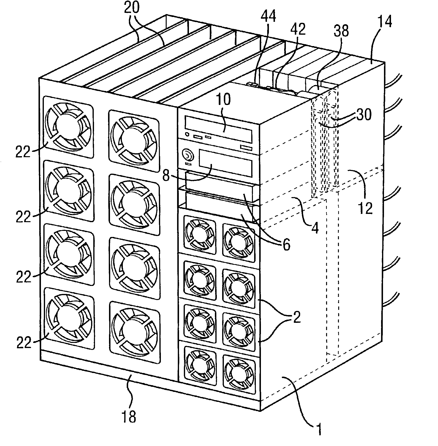
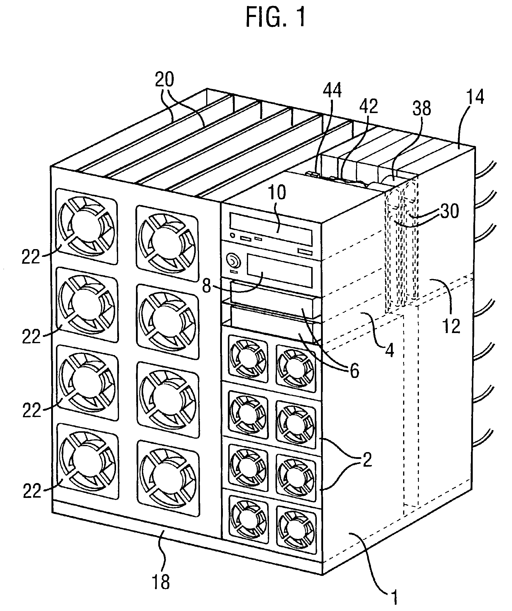
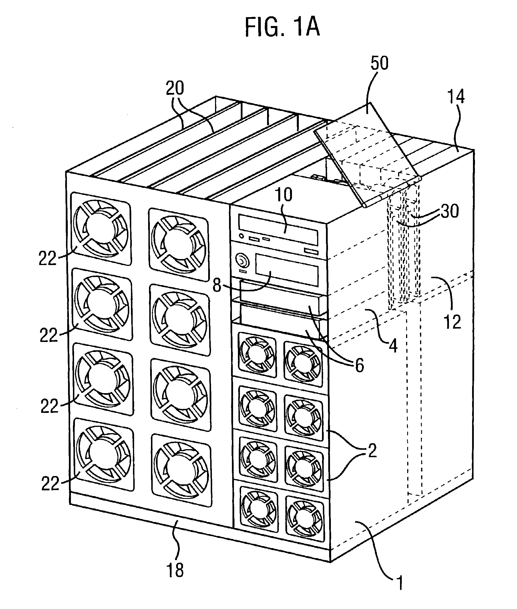
Referring now to the drawings, in which like reference numerals are used to designate corresponding elements, FIG. 1 shows an assembly according to one embodiment of the invention that forms part of a server that may be employed for a number of services, for example as part of a local area network (LAN) or for other telecommunications purposes, and is designed to fit into, for example, a nineteen inch rack electronics cabinet. Other sizes may alternatively be employed, for example to fit into 23 inch or metric racks. The assembly may be designed to be a so-called “RAS” system, that is to say, to have high reliability, availability and serviceability. As such, it is intended that the system will operated with the minimum amount of down time, and so a degree of redundancy is incorporated so that the system will continue to operate even when certain components have failed. In addition, servicing of the equipment should take as short a time as possible, and, where practical, components ...


PUM


Abstract

A chassis for an electronic system. The chassis includes a recess therein for housing a plurality of cooling fans that are arranged in series and can be removed from the recess by sliding out of the recess in a direction across the direction of intended airflow. The assembly is arranged such that any of the fans can be removed and replaced without interrupting operation of the or any other fan. The recess and / or the fans have a seal to prevent or reduce bypass leakage of air around the fans.

Description

BACKGROUND OF THE INVENTIONThe present invention relates to electronics assemblies, and is primarily concerned with thermal management therein. Many such assemblies will be located in racks for housing in for example nineteen inch cabinets, or other size cabinets, in cabinets such as twenty three inch or metric cabinets. The assemblies may for instance be employed as servers for a number of systems, for example in local area networks (LANs), wide area networks (WANs), telecommunications systems or other operations such as database management or as internet servers.Such an assembly will typically comprise a supporting chassis that houses a motherboard or backplane and a number of daughterboards or module cards that extend in planes generally perpendicular to the plane of the motherboard. Because of the amount of heat that is generated during operation of the equipment and the thermal sensitivity of the equipment, it is necessary to provide cooling fans in order to direct a current of...

Claims


Application Information

Patent Timeline
IPC IPC(8): H05K7/20
CPCH05K7/20736H05K7/2019
Inventor OSBORN, JAY KEVINELY, FRAZER
Owner ORACLE INT CORP
Features
  • Generate Ideas
  • Intellectual Property
  • Life Sciences
  • Materials
  • Tech Scout
  • Unparalleled Data Quality
  • Higher Quality Content
  • 60% Fewer Hallucinations
Learn More