Liquid crystal display and method for driving the same

a liquid crystal display and liquid crystal technology, applied in the field of image display devices, can solve the problems of reducing the quality of an image, reducing the number of gray levels in the output image, and reducing the number of gray levels in the image obtained after gamma correction, so as to reduce prevent the effect of lowering the image quality and reducing the number of gray levels

Inactive Publication Date: 2005-04-12
RENESAS ELECTRONICS CORP
View PDF5 Cites 70 Cited by
  • Summary
  • Abstract
  • Description
  • Claims
  • Application Information

AI Technical Summary

Benefits of technology

In view of the above, it is an object of the present invention to provide an LCD and its driving method which enables a proper gamma correction to be made to each of R, G, and B colors without causing a decrease in a number of gray levels in an output image.
With the above configurations, by arranging pixels for each of R, G, and B colors so that pixels in a same color are placed in a scanning direction and by using a different reference gray-scale voltage for each of the R color, G color and B color, since a signal line voltage being matched with a V-T characteristic being different in each of the R, G, and B colors of a liquid crystal panel can be provided, a decrease in a number of gray levels in an output image caused by gamma correction processing can be avoided and lowering in an image quality can be prevented.
With another configuration as above, since image quality data (gamma characteristic for each of the R, G, and B colors) is received and a gamma correction is made to an input image, a change in a relation of the gamma characteristic between the input image and the LCD can be compensated for and therefore lowering in an image quality can be prevented without causing a decrease in the number of gray levels in an output image.
With still another configuration as above, since a gamma correction is made using a reference gray-scale voltage to comparatively a few gray-scale voltage converting points in a wide range in which the gamma correction is made and the gamma correction is made using a gamma value obtained by performing gray-scale data processing from a gamma value at a nearest point in a region between gray-scale voltage converting points, the gamma correction can be made without a decrease in the number of gray levels in an output image using a simple configuration.

Problems solved by technology

However, if the gamma correction is made, by data processing, to input gray-data, a number of gray levels in the gray-scale data obtained after the gamma correction becomes small.
Thus, in the case of the gamma correction by data processing, only gray-scale data that provides direct correspondence between input data and output data is taken out and is used and therefore all the gray-scale values contained in the gray-scale data on a side of input cannot be fully used, which causes lower quality of an image caused by a decrease in a number of gray levels in an output image.
However, in the method in which correction of a gamma characteristic is made by data processing to gray-scale data, as described above, only a portion in which input gray-scale data directly corresponds to output gray-scale data is taken out for use, all the gray-scale data contained in an image signal cannot be used, which causes a decrease in the number of gray levels in an output image after processing of the gamma correction and lowering in an image quality to be displayed.

Method used


Image

  • Liquid crystal display and method for driving the same
  • Liquid crystal display and method for driving the same
  • Liquid crystal display and method for driving the same

Examples


first embodiment

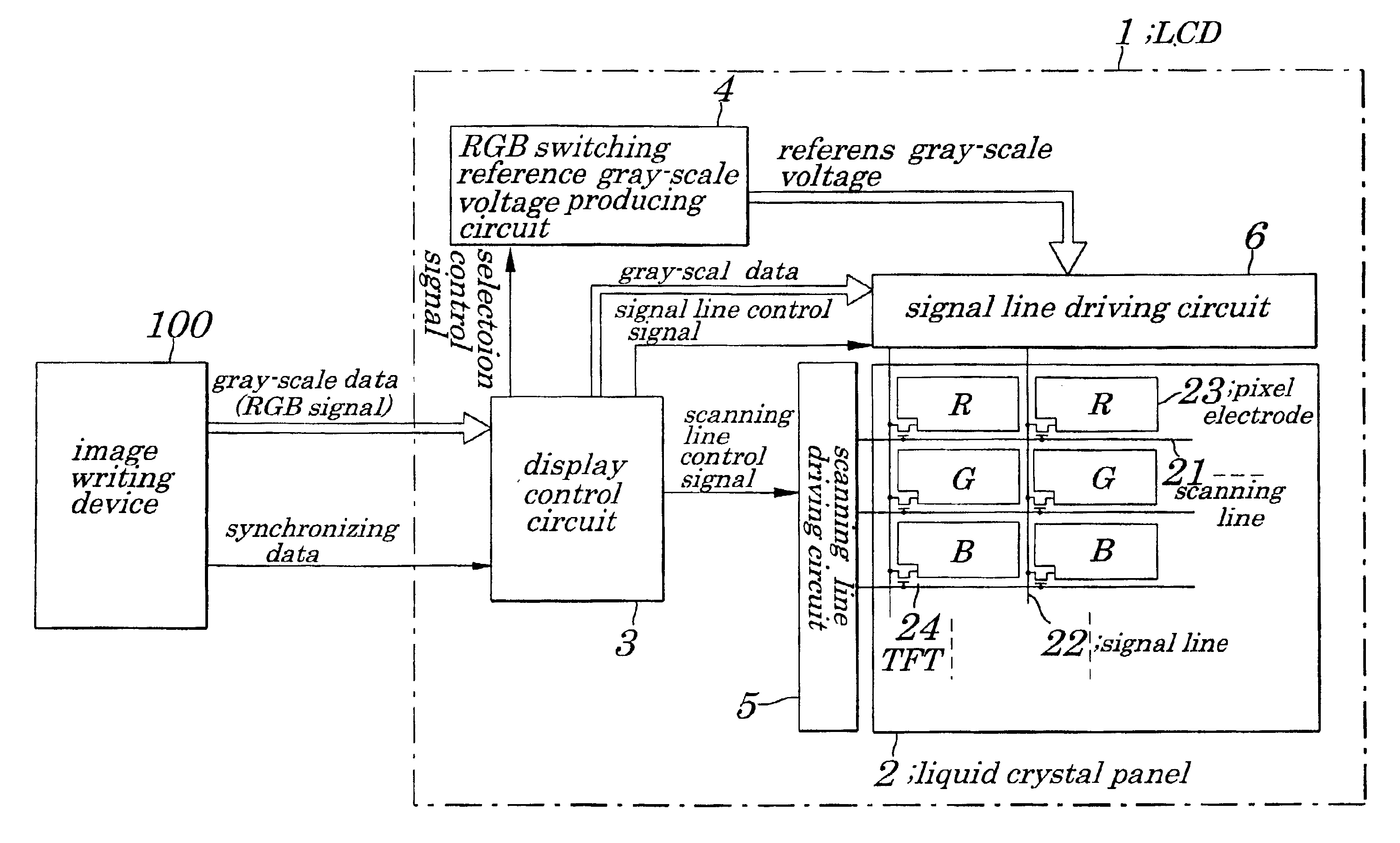
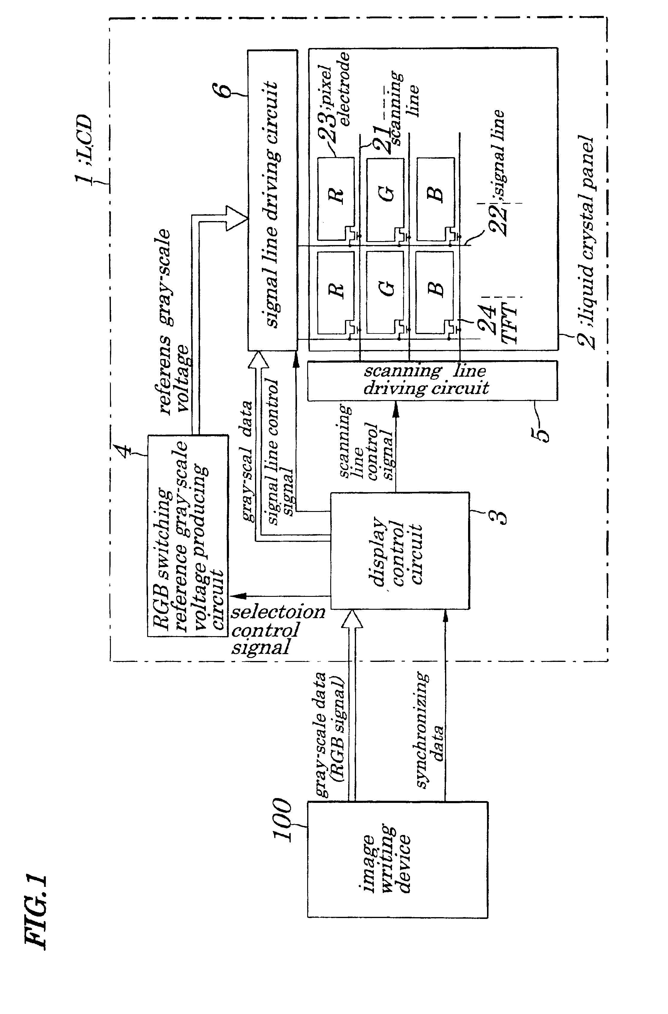
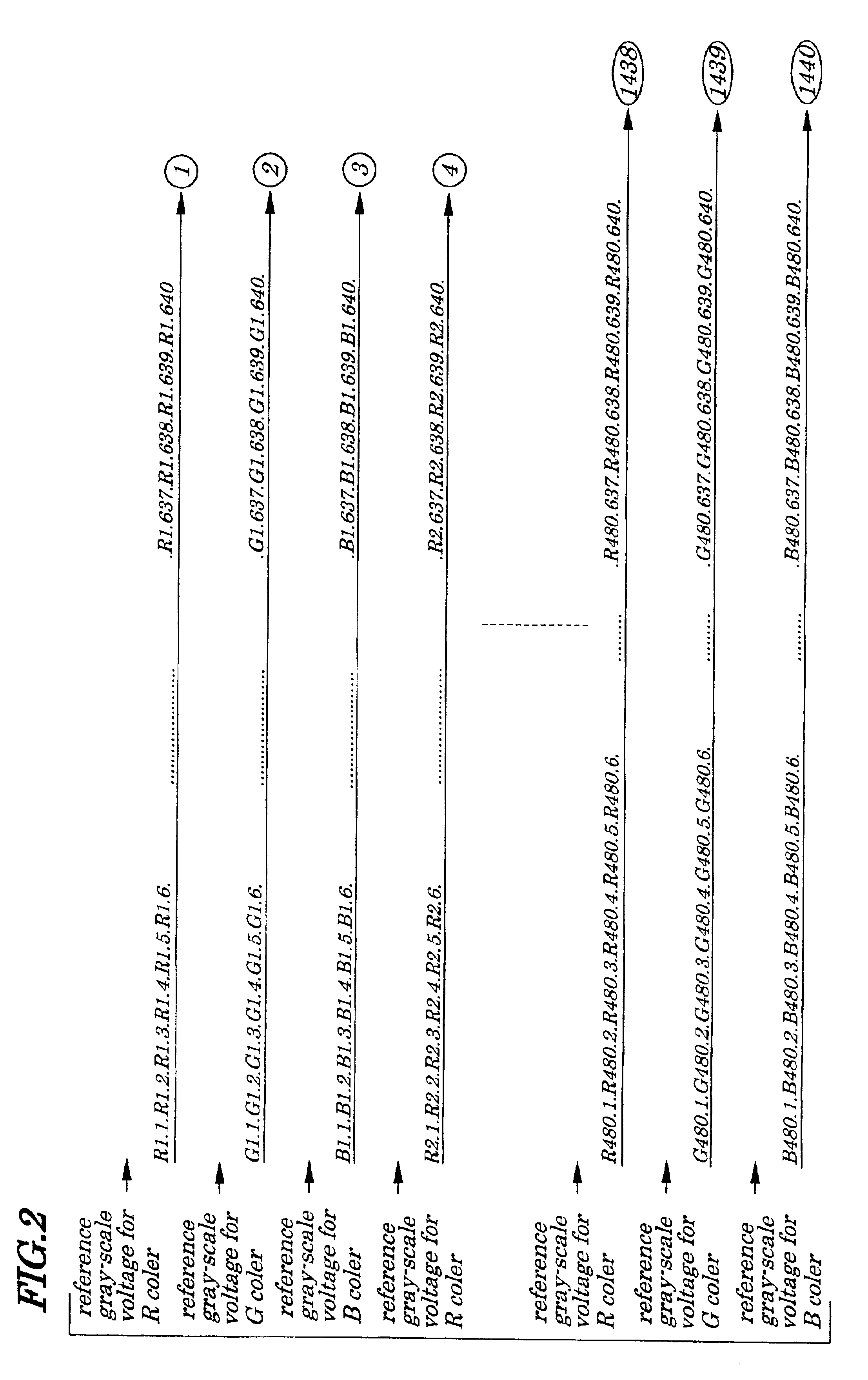
FIG. 1 is a schematic block diagram showing configurations of an LCD of a first embodiment of the present invention. FIG. 2 is a diagram illustrating a sorted state of gray-scale data according to the first embodiment. FIG. 3 is a schematic block diagram showing a concrete example of configurations of an RGB switching reference gray-scale voltage producing circuit 4 and a signal line driving circuit 6 of the first embodiment.FIG. 4 is a diagram illustrating a reference gray-scale voltage for each color employed in the first embodiment. FIG. 5 is a diagram illustrating a gamma characteristic of each color employed in the first embodiment.

The LCD 1 of the first embodiment chiefly includes a liquid crystal panel 2, a display control circuit 3, an RGB (Red, Green, and Blue) switching reference gray-scale voltage producing circuit 4, a scanning line driving circuit 5 and a signal line driving circuit 6.

Configurations of the liquid crystal panel 2 are same as those of the conventional one...

second embodiment

FIG. 6 is a schematic block diagram showing configurations of an LCD 1A according to a second embodiment of the present invention. FIG. 7 is a schematic block diagram showing a concrete example of configurations of a DAC-contained reference gray-scale voltage producing circuit 4A, a scanning reference gray-scale voltage producing circuit 4A and a signal line driving circuit 6 according to the second embodiment.

The LCD 1A of the second embodiment, as shown in FIG. 6, chiefly includes a liquid crystal panel 2 a display control circuit 3A, the DAC-contained reference gray-scale voltage producing circuit 4A, a scanning line driving circuit 5, and the signal line driving circuit 6. Configurations of the liquid crystal panel 2, scanning line driving circuit 5, and signal line driving circuit 6 are same as those in the first embodiment shown in FIG. 1 and descriptions of them are omitted accordingly.

In the second embodiment, an image writing device 100A outputs, in addition to gray-scale d...

third embodiment

FIG. 8 is a schematic block diagram showing configurations of an LCD 1B according to a third embodiment of the present invention. FIG. 9 is a diagram illustrating a decrease in a number of gray levels in an output image caused by a gamma correction in the third embodiment.

The LCD 1B of the third embodiment, as shown in FIG. 8, chiefly includes a liquid crystal panel 2, a display control circuit 3A, a DAC-contained reference gray-scale voltage producing circuit 4A, a scanning line driving circuit 5, a signal line driving circuit 6, and an image processing circuit 7. Configurations of the liquid crystal panel 2, display control circuit 3A, scanning line driving circuit 5, and signal line driving circuit 6 are same as those in the second embodiment shown in FIG. 7 and detailed descriptions are omitted accordingly.

In the case where a range of the gamma correction is wide such as a range for a gamma correction (0.20 to 3.00) in a property on a screen of Windows, a reference gray-scale vo...


PUM

PropertyMeasurementUnit
colorsaaaaaaaaaa
voltage-transmittanceaaaaaaaaaa
gray-scale voltageaaaaaaaaaa

Abstract

A liquid crystal display and its driving method are provided which enable a proper gamma correction to be made to each of red, green, and blue colors without causing a decrease in a number of gray levels in an output image and enable lowering in an image quality to be prevented. The liquid crystal display includes a liquid crystal panel in which pixel electrodes for each of the red, green, and blue colors are repeatedly arranged along a scanning line, a scanning line driving circuit to scan in every scanning period, an RGB (Red, Green, and Blue) switching reference gray-scale voltage producing circuit to produce a reference voltage corresponding to a voltage-transmittance characteristic of each color, and a signal line driving circuit to produce a signal voltage and to feed to each signal line.

Description

BACKGROUND OF THE INVENTION1. Field of the InventionThe present invention relates to an image display device and more particularly to a liquid crystal display (LCD) and its driving method in which an image signal to be fed to a liquid crystal panel is produced using a reference gray-scale voltage and gray-scale data.The present application claims priority of Japanese Patent Application No. 2001-136740 filed on May 7, 2001, which is hereby incorporated by reference.2. Description of the Related ArtIn an LCD, display of an image is performed by using a liquid crystal panel as a display device. The liquid crystal panel is so configured that a first glass substrate on which a pixel electrode made up of a transparent electrode is placed in a manner to correspond to pixels arranged in a matrix form on a display surface faces a second glass substrate on which a common electrode made up of a transparent electrode with a liquid crystal substance being a crystalline liquid that provides optic...

Claims


Application Information

Patent Timeline
Patent Type & Authority Patents(United States)
IPC IPC(8): G09G3/36G09G3/20G02F1/133H04N5/66H04N9/30
CPCG09G3/3607G09G3/3688G09G3/3696G09G2320/0276G09G2310/027G02F1/133
Inventor NOSE, TAKASHI
Owner RENESAS ELECTRONICS CORP
Why Eureka
Try Eureka