Method and device for measuring the diameter of a peripheral rod in a fuel assembly of a nuclear reactor

Inactive Publication Date: 2005-04-12
FRAMATOME ANP
View PDF25 Cites 12 Cited by
  • Summary
  • Abstract
  • Description
  • Claims
  • Application Information

AI Technical Summary

Benefits of technology

The object of the invention is thus to propose a method of measuring the diameter of a peripheral rod of a fuel assembly of a nuclear reactor cooled by light water, the fuel assembly comprising a bundle of fuel rods and a framework for supporting the fuel rods, the framework comprising spacer grids distributed in an axial longitudinal direction of the bundle of rods, guide tubes disposed in certain positions of the rods inside the bundle, and end nozzles, the measurement being performed underwater in a pool in which the fuel assembly is placed so that its longitudinal axis extends vertically, and being performed between two successive spacer grids along a longitudinal segment of a rod situated at the periphery of the fuel assembly, which method makes it possible to perform highly accurate measurements remotely and without taking the fuel assembly apart.

Problems solved by technology

In a nuclear reactor in operation, the fuel assemblies are subjected to irradiation which leads to certain modifications in the structure and size of the elements constituting the fuel assembly.
This results in the tubular cladding of the rods deforming and in an increase in the diameter of the rods.
As a result, the rods are caused to vibrate and are therefore subject to a certain amount of wear where they come into contact with the dimples inside the spacer grids.
Nevertheless, a method has not been known in the past enabling the diameter of peripheral rods to be measured with very high measurement accuracy in a fuel assembly along those segments of the rod that extend between two successive spacer grids or along those segments of the rods that are received inside the spacer grids and that are subjected to wear in the reactor in operation, without it being necessary to take the fuel assembly apart.

Method used


Image

  • Method and device for measuring the diameter of a peripheral rod in a fuel assembly of a nuclear reactor
  • Method and device for measuring the diameter of a peripheral rod in a fuel assembly of a nuclear reactor
  • Method and device for measuring the diameter of a peripheral rod in a fuel assembly of a nuclear reactor

Examples


Embodiment Construction

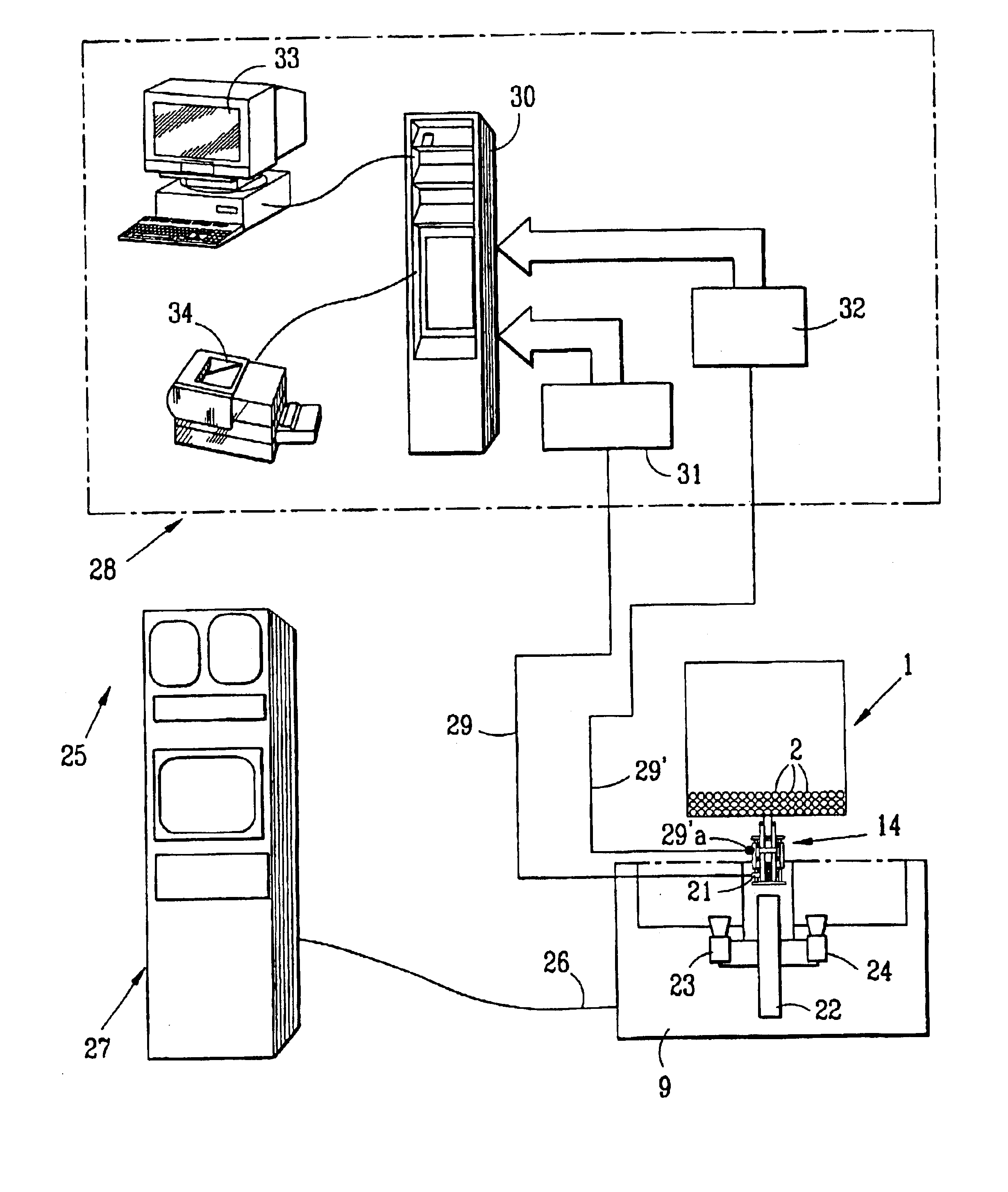
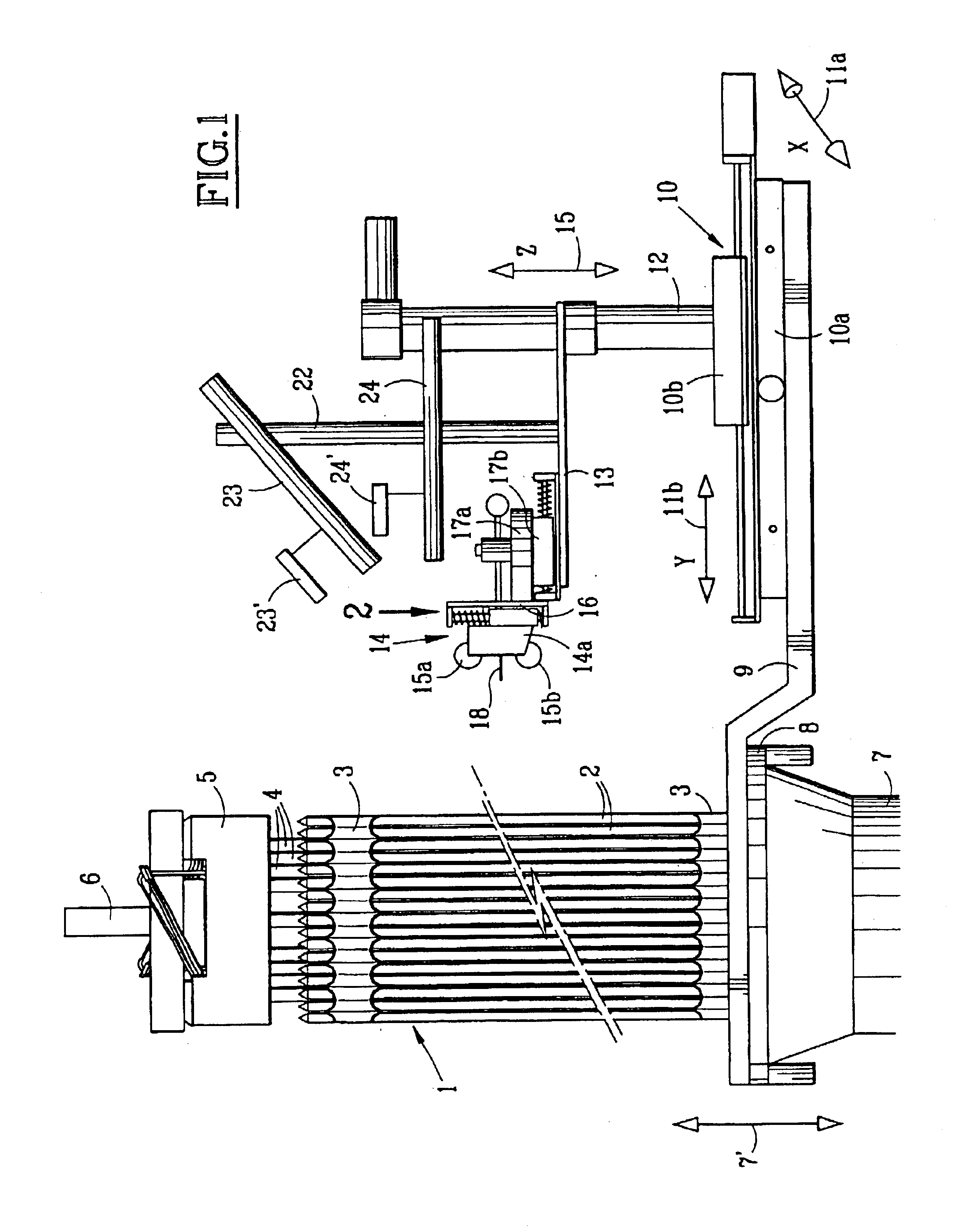
FIG. 1 illustrates a portion of a fuel assembly 1 for a pressurized water cooled reactor, the assembly being partially engaged in a fuel elevator 7 of the deactivation pool of a nuclear power station.

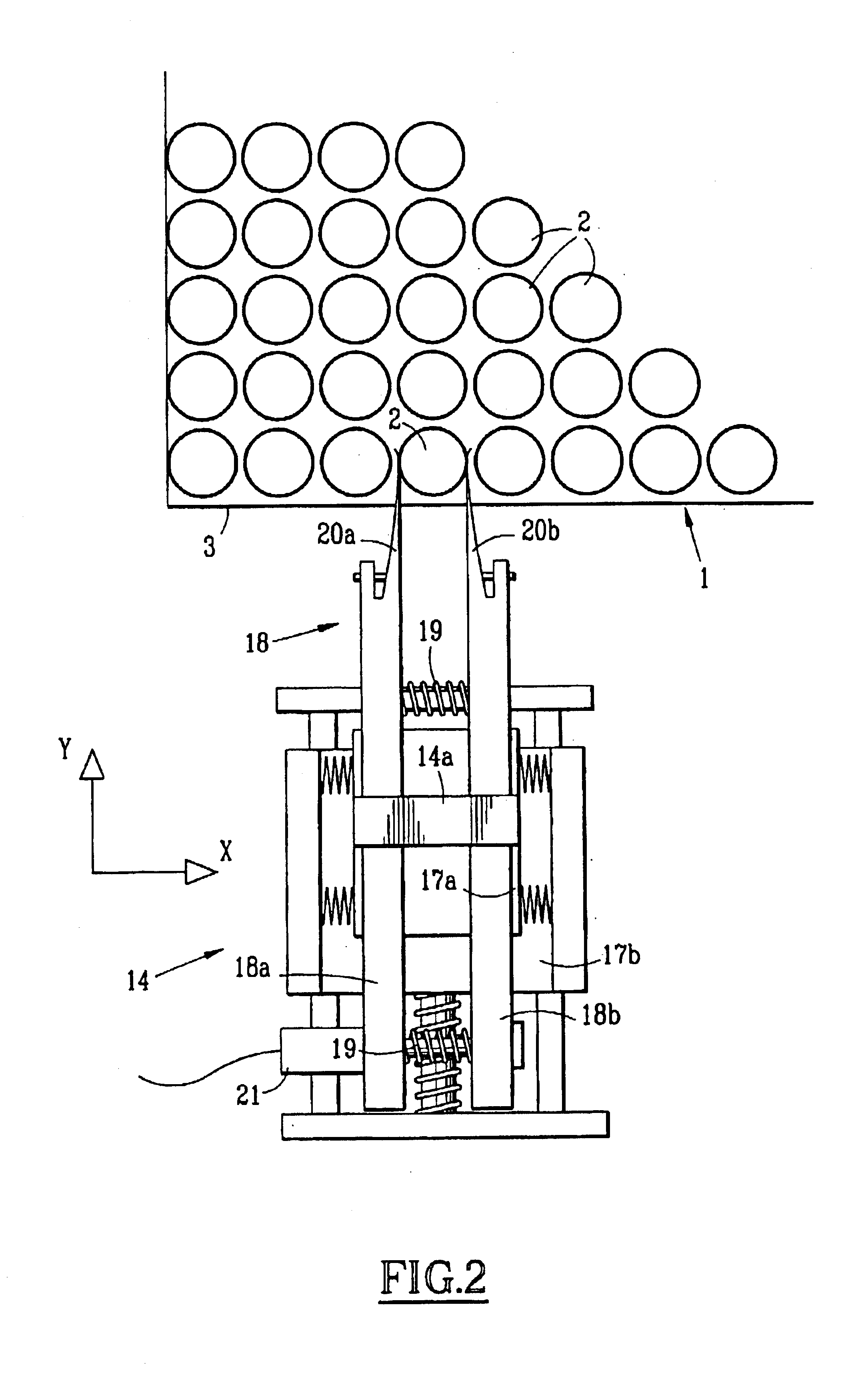
The fuel assembly 1 comprises a bundle of rods 2 and a framework comprising spacer grids 3 for supporting the rods 2, guide tubes 4, and nozzles fixed to the end portions of the guide tubes 4 at opposite ends of the bundle of rods 2.

In FIG. 1, the top end nozzle 5 of the fuel assembly is illustrated with the fuel assembly being suspended via said nozzle from a sling 6 of a handling device supported by a pit bridge above the top level of the pool.

The fuel assembly which is fully immersed in the water of the pool is disposed with its longitudinal axis parallel to the direction of the fuel rods 2 in the bundle, in a vertical direction, and is inserted in part into the elevator 7 via the top end of the elevator which may be moved vertically, as represented diagrammatically by double-headed ...


PUM


Abstract

The diameter of a segment of a peripheral rod in a fuel assembly is measured between two successive spacer grids. A measuring tool is positioned at a level situated between the two successive spacer grids, the tool comprising two measuring fingers that are free to move relative to each other in a first horizontal direction and that are urged towards each other by a resilient return arrangement, and that extend in a second horizontal direction perpendicular to the first horizontal direction. The measuring fingers are moved in the second horizontal direction towards a rod so as to put two contact pieces of the measuring fingers into contact with two zones of the rod segment. The measuring fingers are moved in the vertical axial direction of the rod along its segment situated between the two spacer grids and an electromagnetic sensor is used to measure the distance between the measuring fingers in the first horizontal direction while the measuring fingers are being moved axially.

Description

FIELD OF THE INVENTIONThe invention relates to a method and to a device for measuring the diameter of a peripheral rod of a fuel assembly of a nuclear reactor that is cooled with light water, and in particular a fuel assembly for a nuclear reactor that is cooled with pressurized water.BACKGROUND INFORMATIONThe fuel assemblies for reactors cooled with light water and in particular the fuel assemblies for reactors cooled with pressurized water generally comprise a bundle of fuel rods each made up of a stack of pellets of fuel material inside tubular cladding, and a framework for supporting the fuel rods, the framework comprising spacer grids that are spaced apart along the rods of the bundle, guide tubes that occupy certain rod positions inside the bundle, and two end nozzles.Inside the bundle, the fuel rods are supported in parallel dispositions by the spacer grids which are constituted by respective square-mesh arrays of square cells, each of which has a fuel rod engaged therein, or...

Claims


Application Information

Patent Timeline
IPC IPC(8): G21C17/06
CPCG21C17/06G21Y2002/402G21Y2002/401G21Y2002/204Y02E30/30
Inventor ARIAS, JAIROMAIRE, SANDRINE
Owner FRAMATOME ANP
Why Eureka
Try Eureka