
Pressure-stable cylinder

a technology of pressure-stable cylinders and pressure-stable cylinders, which is applied in the direction of mechanical equipment, transportation and packaging, and discharging methods of containers, etc., can solve the problems of insufficient pressure of air inflation chamber ii, water and air possibly draining out, and it is impossible to clean and maintain the pressure-stable cylinder and update the parts of the pressure-stable cylinder

Inactive Publication Date: 2005-04-19
LIN MAO CHANG
View PDF7 Cites 5 Cited by
  • Summary
  • Abstract
  • Description
  • Claims
  • Application Information

AI Technical Summary

Benefits of technology

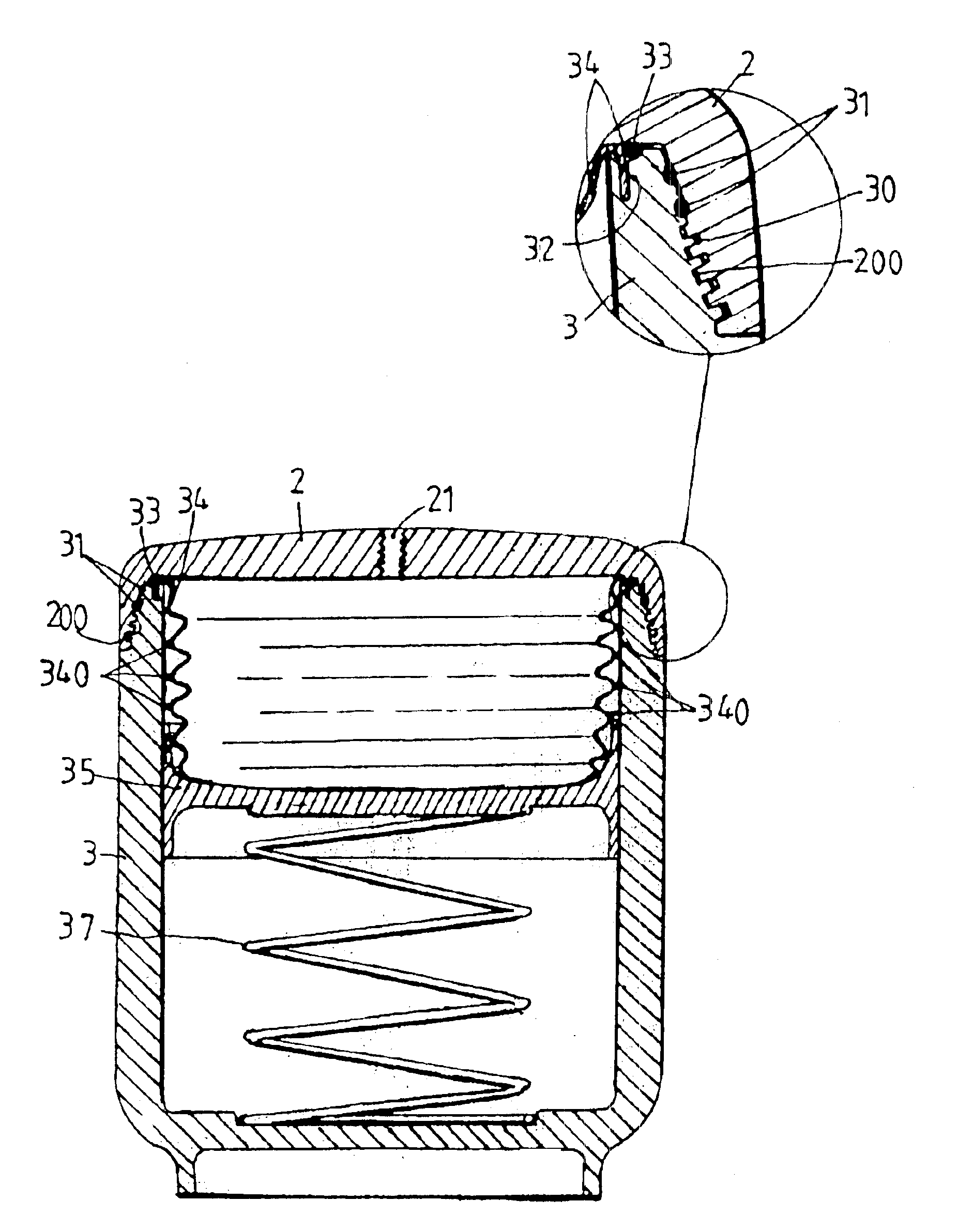
[0017]Accordingly, the primary object of the present invention is to provide a pressure-stable cylinder which comprises a cover having a dome shape groove and a through hole; an inner wall of the dome shape groove having threads; a cylinder having an opening and an opening section around the opening having a threaded tapered shape matching to the dome shape groove of the cover; the opening section of the cylinder being formed with a plurality of first washers; one end of the opening section having a coupling groove and a second washer; the washers have the effect of air-tightness and convenience of detaching and separation for maintenance; a bellow coupled to the second washer; a disk placed below the bellow; and a compressible spring placed between the disk and a bottom of the cylinder; the compressible spring resisting against the disk so that the cylinder has a predetermined pressure.

Problems solved by technology

Thereby, water and air possibly drain out.
Thereby, air in the air inflation chamber II possibly vents out so that the pressure of the air inflation chamber II is insufficient.
Therefore, it is impossible to clean and maintain the pressurized cylinder and to update the parts of the pressurized cylinder.
In this prior art pressure-stable cylinder, since many parts are used, which are made singly so that air easily drains out so that the function of buffering water pressure is lost.
If it is used for a long time, it easily rusts so that the air pressure is insufficient and thus the buffering function is lost.

Method used


Image

  • Pressure-stable cylinder
  • Pressure-stable cylinder
  • Pressure-stable cylinder

Examples


Embodiment Construction

[0031]Referring to FIGS. 6 and 7, the pressure-stable cylinder of the present invention is illustrated. The pressure-stable cylinder comprises a cover 2 and a cylinder 3.

[0032]The cover 2 has a dome shape groove 20 and a through hole 21. An inner wall of the dome shape groove 20 has threads 200.

[0033]The cylinder 3 has an opening. An opening section of the cylinder 3 has a threaded tapered shape matching to the dome shape groove 20 of the cover 2. The opening section of the cylinder 3 is formed with a plurality of washers 31. The end of the opening section has a coupling groove 32 and a washer 33 for coupling a telescopic bellow 34. The washers 31, 33 have the effect of air-tightness and convenience of detaching and separation for maintenance. A plurality of stepped sections 30 are formed around the opening section for receiving the washers 31, 33.

[0034]An outer wall of the bellow 34 is formed with strips which can be helical threads or a plurality of round flange 340 or a plurality...


PUM


Abstract

A pressure-stable cylinder comprises a cover having a dome shape groove and a through hole; an inner wall of the dome shape groove having threads; a cylinder having an opening and an opening section around the opening having a threaded tapered shape matching to the dome shape groove of the cover; the opening section of the cylinder being formed with a plurality of first washers; one end of the opening section having a coupling groove and a second washer; a bellow coupled to the second washer; a disk placed below the bellow; and a compressible spring placed between the disk and a bottom of the cylinder; the compressible spring resisting against the disk so that the cylinder has a predetermined pressure. In assembly, the washer and the bellow are steadily fixed to the coupling groove of the cylinder. The washers have an effect of draining-proof and air-tightness.

Description

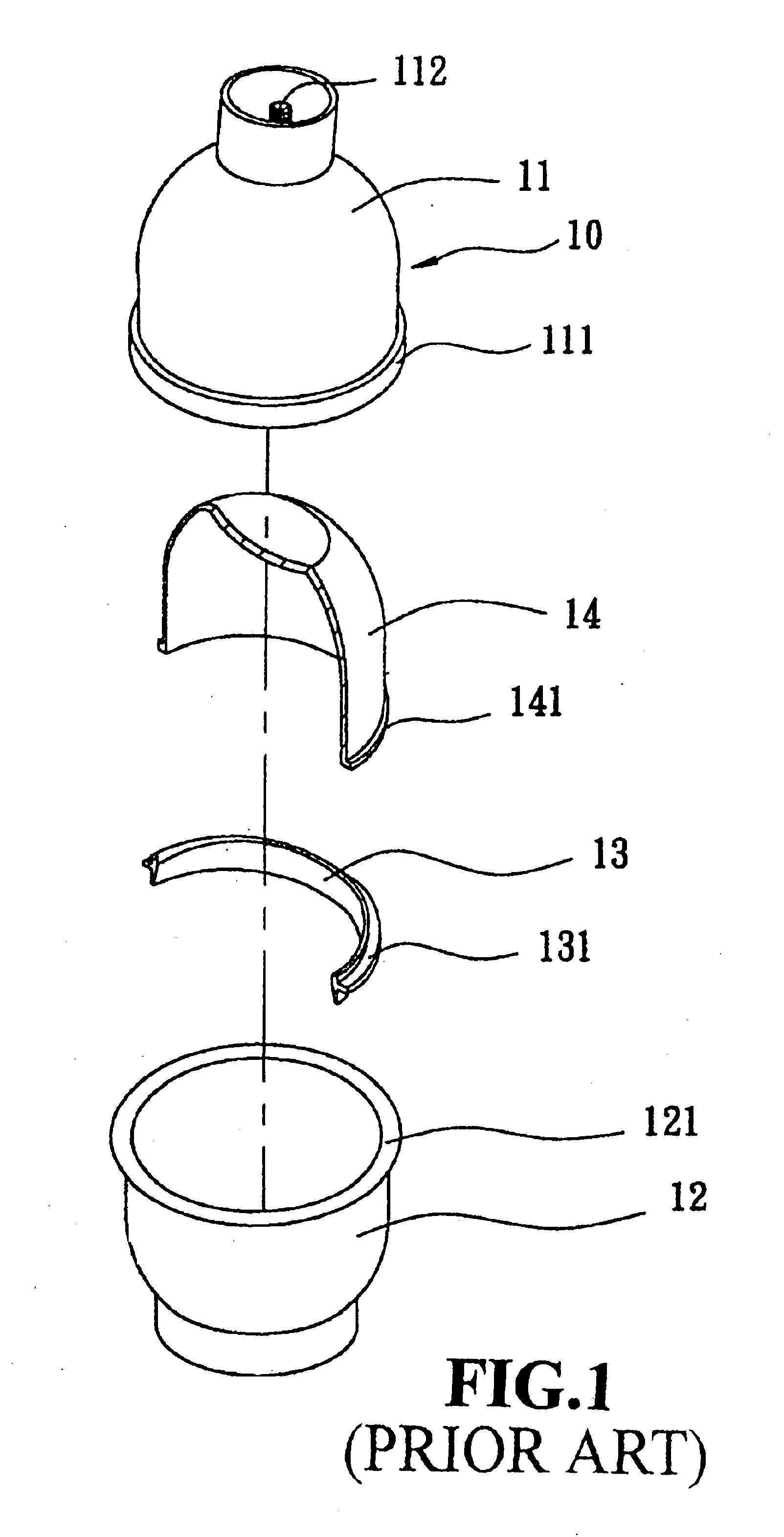
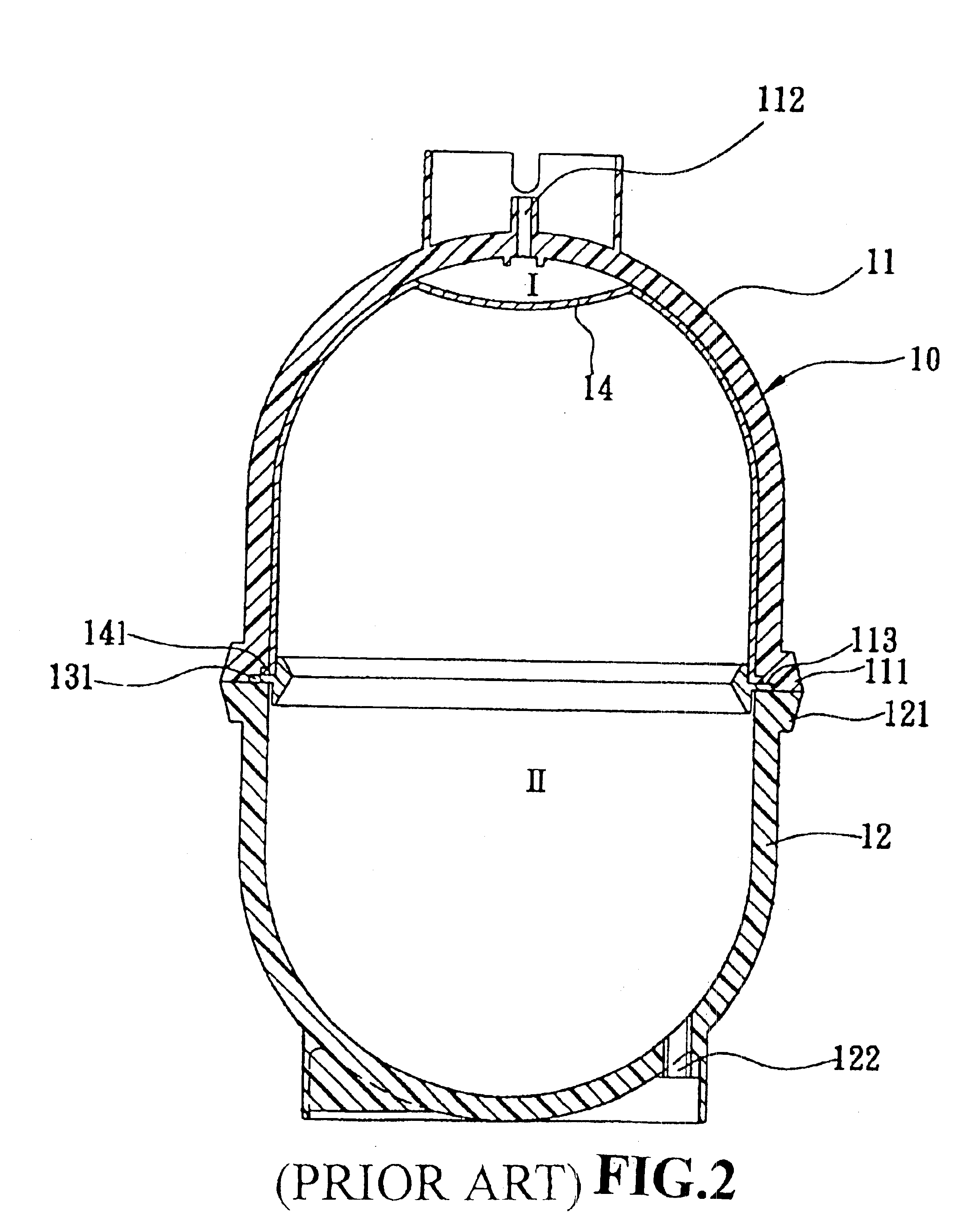
FIELD OF THE INVENTION[0001]The present invention relates to pressure-stable cylinders, and particularly to a pressure-stable cylinder which can be operated steadily.BACKGROUND OF THE INVENTION[0002]Referring to FIGS. 1 and 2, a prior art reverse osmosis pressurized cylinder is illustrated. The pressurized cylinder is formed by an upper cover 11, a lower seat 12, a buckling ring 13 and an inflation isolating film 14.[0003]The upper cover 11 and lower seat 12 are made of plastics or metals. The interiors of the upper cover 11 and lower seat 12 are concave. An openings of the upper cover 11 and lower seat 12 are formed with flanges 111, 121. A top of the upper cover 11 is formed with a water inlet 112 for be connected to the water inlet valve (not shown). An inner side near the opening of the upper cover 11 has a concave wedge surface 113.[0004]A lower end of the lower seat 12 is installed with an air inflation mouth 122 for assembling an air inflation valve. An edge of the opening of...

Claims


Application Information

Patent Timeline
Patent Type & Authority Patents(United States)
IPC IPC(8): F16L55/04F16L55/053
CPCF16L55/053
Inventor LIN, MAO CHANG
Owner LIN MAO CHANG
Learn More