Weft end collector

Inactive Publication Date: 2005-04-19
TSUDAKOMA KOGYO KK
View PDF13 Cites 2 Cited by
  • Summary
  • Abstract
  • Description
  • Claims
  • Application Information

AI Technical Summary

Benefits of technology

[0016]The switching mechanism can include a common case where all the storing and dewatering sections are disposed, and the case can be moved so as to switch the storing and dewatering sections to receive the water. This enables to recover the weft ends by moving the case, then by moving the storing and dewatering section which should recover the weft ends to a position where this section gets in the non-watery state but where the weft end carrier and other devices do not prevent the recovering work, thereby facilitating the recovering work. Also, since all the plural storing and dewatering sections are integrally moved by the common case, all the plural storing and dewatering sections are simultaneously moved at the time of switching, thereby making the switching smoothly.
[0017]In the weft end recovery apparatus, the case can be made to rotate so as to switch the storing and dewatering sections to receive the water. Thus,

Problems solved by technology

Consequently, according to the conventional weft end recovery apparatus, an operator cannot avoid contacting the water and the weft ends dropping from above when taking out and recovering the weft ends from a storing and dewatering section, as a result of which they bound and scatter around the recovery apparatus.
Further, the scattered weft ends get dirty with oil, dust, etc., aro

Method used


Image

  • Weft end collector
  • Weft end collector
  • Weft end collector

Examples


Example

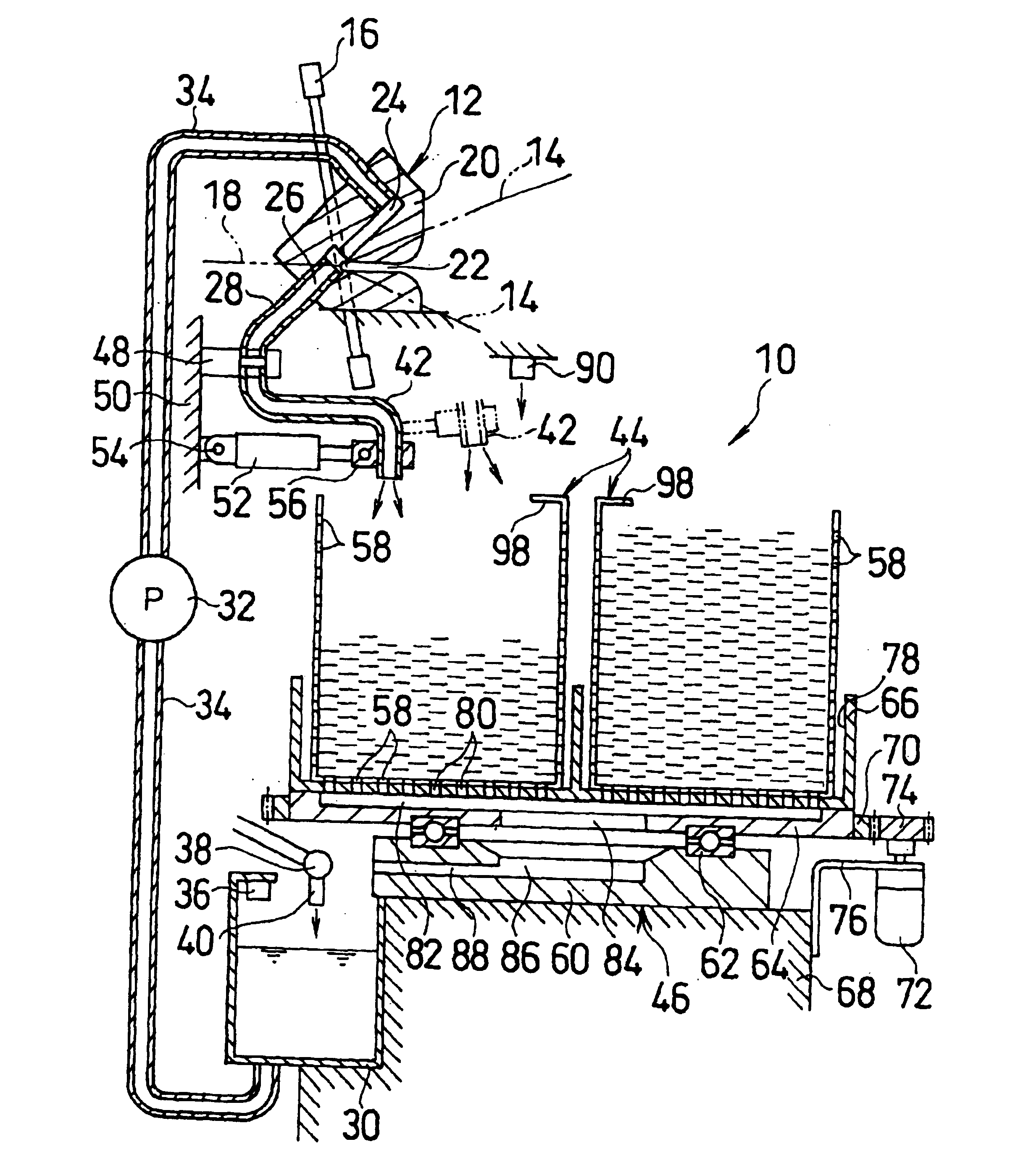
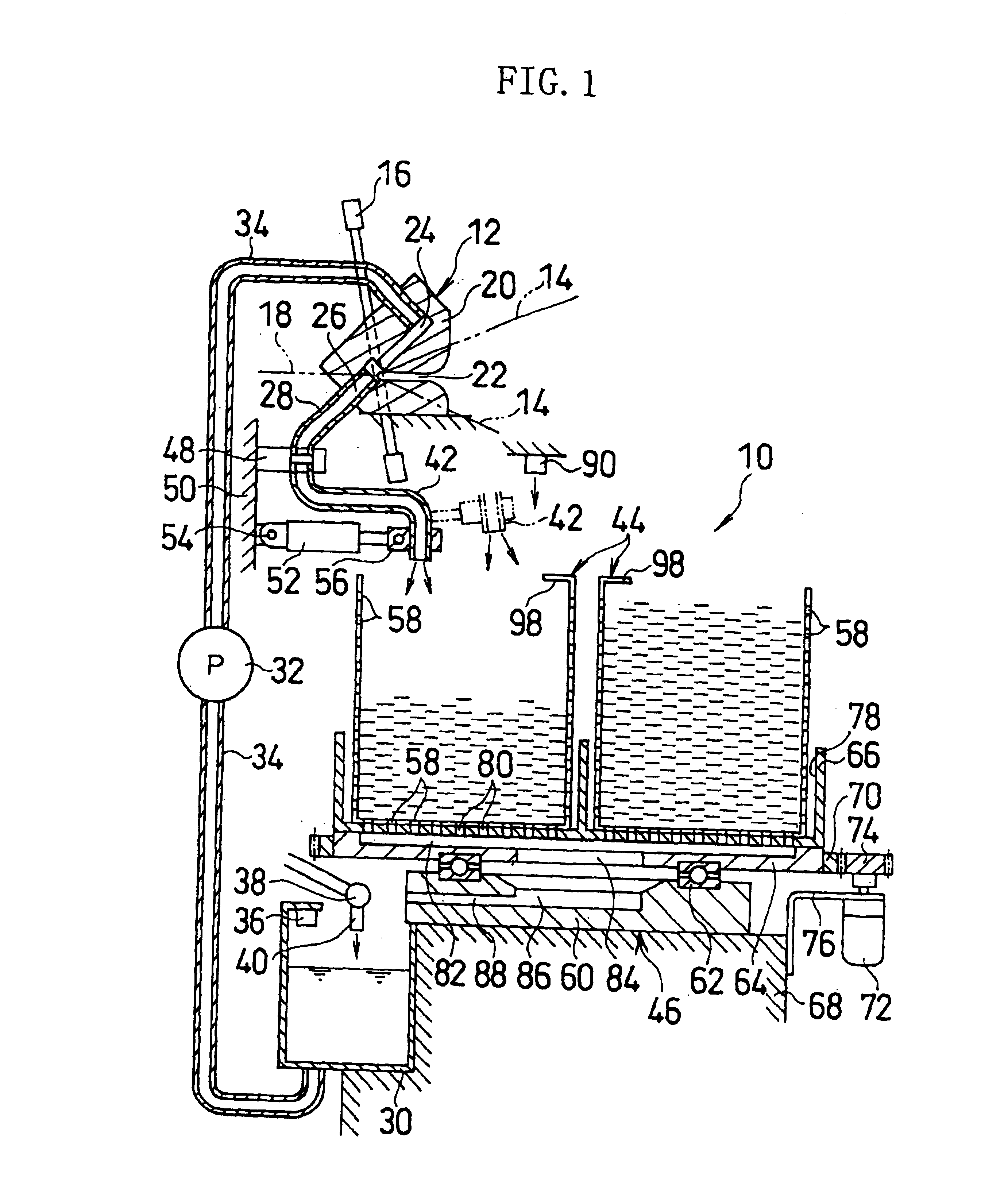
[0023]Referring to FIGS. 1-3, the weft end recovery apparatus 10 is applied to a water jet loom together with a weft end processing device 12.

[0024]The water jet loom inserts the weft (not shown) from a weft insert nozzle (not shown) into a shedding of the warp 14 by pressure water, restrains and holds the front end of the inserted weft by the weft end processing device 12, and beats the weft in that state against a cloth fell by a reed to form a fabric 18. The beaten weft front ends are cut away from the fabric 18, thereby forming weft ends.

[0025]The weft end processing device 12 includes a block-shaped weft catching bracket 20 for catching the front ends of the weft. The catching bracket 20 makes the weft front ends pass by receiving the front ends of the weft to be beaten into a slit 22 and discharging the pressure water from a discharge channel 24 via the back of the slit 22 into an exhaust channel 26. Thus, the weft front ends are brought into contact with the pressure water at...


PUM


Abstract

A weft end recovery apparatus comprises weft end carrier for carrying by water flow weft ends formed as a result of weft insertion, a plurality of storing and dewatering sections to receive the weft ends carried from the weft end carrier together with the water, and switching mechanism for selectively switching the storing and dewatering sections to store the weft ends and the water from the weft end carrier.

Description

BACKGROUND OF THE INVENTION[0001]1. Field of the Invention[0002]The present invention relates to a weft end recovery apparatus in a fluid jet loom for carrying and recovering by a water flow weft ends caused by weft insertion.[0003]2. Description of Prior Art[0004]In a fluid jet loom such as a water jet loom, the weft is inserted into a shedding of the warp, followed by reed beating, and then cut away from a fabric. For this reason, a fluid jet loom is generally provided with a device for recovering weft ends cut away from a fabric.[0005]As one of such weft end recovery apparatuss, there is disclosed a apparatus which carries weft ends cut away from a fabric by a carrier device using a water flow and recovers the weft ends into a recovery vessel by flowing them down from above the vessel together with water (Japanese Patent Appln. Public Disclosure (KOKAI) No. 10-195739).[0006]In this conventional weft end recovery apparatus, the recovery vessel separates the weft ends and the water...

Claims


Application Information

Patent Timeline
IPC IPC(8): D03D47/32D03D47/28D03J1/00D03J1/04D03D47/36
CPCD03D47/32D03J1/04D03J1/00
Inventor MYOGI, KEIICHI
Owner TSUDAKOMA KOGYO KK
Why Eureka
Try Eureka