Full bore automatic gun release module

a full-bore, automatic technology, applied in the direction of borehole/well accessories, drilling pipes, drilling casings, etc., can solve the problems of inability to fully discharge the gun, the downhole environment of deep earth boring is often hostile to extremes, and the ignition system, explosives or propellant charges are sometimes compromised

Inactive Publication Date: 2005-04-19
BAKER HUGHES INC
View PDF23 Cites 29 Cited by
  • Summary
  • Abstract
  • Description
  • Claims
  • Application Information

AI Technical Summary

Benefits of technology

[0022]When the spent gun shifts downwardly, the profiled upper latch tube is pulled down to shear the respective retaining pin and remove the radial support structure under the upper latch pins. Without interior support, the upper latch pins retract radially inward to rel

Problems solved by technology

The downhole environment of a deep earth boring is frequently hostile to the extreme.
Consequently, by the time the perforating gun arrives at the desired perforation location, the ignition system, the explosives or the propellant charges are sometimes compromised to the extent that discharge fails to occur on comma

Method used


Image

  • Full bore automatic gun release module
  • Full bore automatic gun release module
  • Full bore automatic gun release module

Examples


Embodiment Construction

CONSTRUCTION AND ASSEMBLY

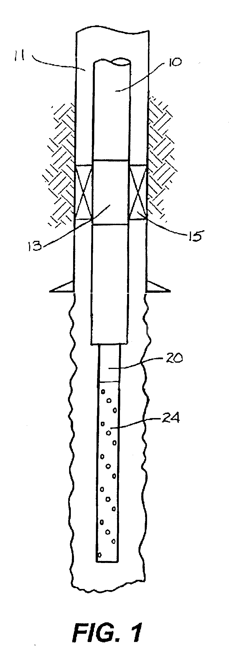
[0035]The invention is shown schematically by FIG. 1 to include production tubing 10 suspended within a wellbore 11. The production tubing may be secured to the wellbore wall by anchoring slip elements of a production packer joint 13. An annular space between the packer joint outer perimeter and the inside wellbore wall is bridged by expansible packer seal elements 15. This bridge across the wellbore annular space isolates the well production zone below the packer joint 13 from the wellbore space above the packer joint 13.

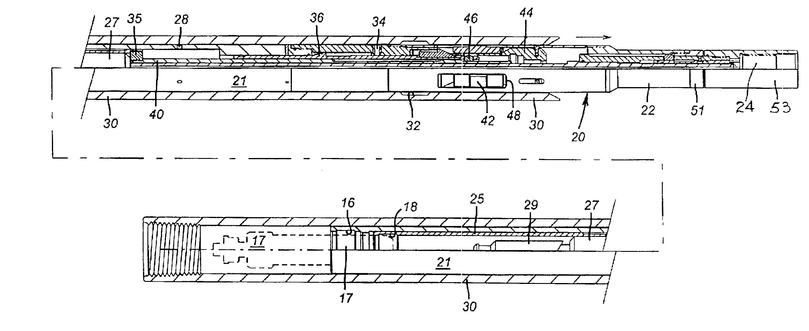
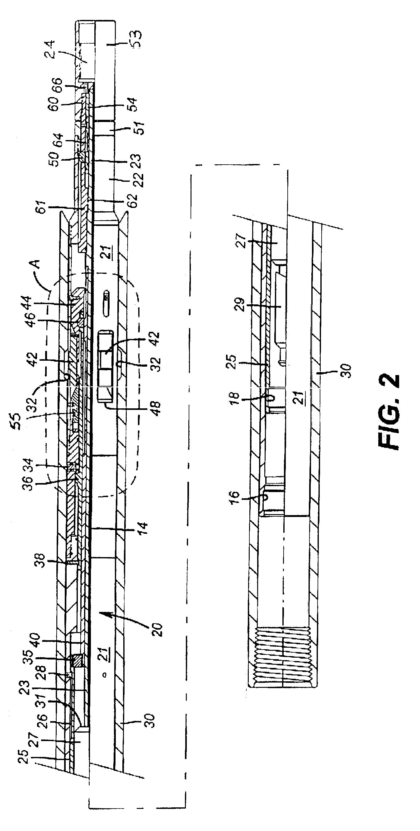
[0036]Although the invention operating environment may include substantially horizontal wellbore orientation, references herein to “upper” and “lower” are generally related to the wellbore surface direction. Accordingly, the left end of the FIGS. 2 through 10 illustrations normally represents the “upper” end direction of the assembly. Descriptive references to “up” and “down” hereafter will be consistent with this orientation.

[0037]Below th...


PUM


Abstract

A well completion procedure and apparatus comprises a first assembly that includes production tubing combined with a production packer and an internal bore latching profile. A second assembly comprises an explosive perforating gun secured to a latching mechanism. The perforating gun and latching mechanism are dimensioned to freely traverse the flow bore of the production tubing for downhole retrieval and return after the packer is set. The latching mechanism may be released by discharge of the gun.

Description

CROSS-REFERENCE TO RELATED APPLICATIONS[0001]This application is a Continuation-In-Part of U.S. patent application Ser. No. 10 / 002,791 filed Nov. 15, 2001 now U.S. Pat. No. 6,591,912. Said application Ser. No. 10 / 002,791 claims the filing priority date of Nov. 15, 2000 based upon U.S. Provisional Application Ser. No. 60 / 248,810.BACKGROUND OF THE INVENTION[0002]1. Field of the Invention[0003]The present invention relates to the art of well drilling and earth boring. More particularly, the invention relates to methods and apparatus for perforating wellbore casing, casing liner and / or fracturing well production zones.[0004]2. Description of Related Art[0005]After the actual drilling of a borehole into the earth, the borehole shaft is often prepared for long term fluid production by a series of steps and procedures that are collectively characterized by the art as “completion.” Among these numerous procedures is the process of setting a casing, usually steel, within the borehole to line...

Claims


Application Information

Patent Timeline
IPC IPC(8): E21B23/00E21B17/06E21B23/04E21B23/02E21B17/02E21B43/11E21B43/119
CPCE21B17/06E21B43/119E21B23/04E21B23/02E21B43/1193E21B23/0414
Inventor MYERS, JR., WILLIAM D.ROSS, COLBY W.
Owner BAKER HUGHES INC
Why Eureka
Try Eureka