Air-intake structure around front grille for vehicle

a technology for air intake and vehicle, which is applied in the direction of roofs, transportation and packaging, vehicle arrangements, etc., can solve the problems of increasing the number of components and complex structure, and achieve the effect of further increasing the separation effect of foreign matter mixed in the running air from the same running air

Inactive Publication Date: 2005-04-19
HONDA MOTOR CO LTD
View PDF17 Cites 52 Cited by
  • Summary
  • Abstract
  • Description
  • Claims
  • Application Information

AI Technical Summary

Benefits of technology

[0020]Foreign matters such as rain water and dust which are mixed in the running air flowing to the transverse direction through the air-induction space can be s...

Problems solved by technology

In the prior art, however, since the seal board right-hand division unit 105A and the seal board left-hand division unit 105B are cons...

Method used


Image

  • Air-intake structure around front grille for vehicle
  • Air-intake structure around front grille for vehicle
  • Air-intake structure around front grille for vehicle

Examples


Embodiment Construction

[0030]An embodiment of the invention will be described below based on the accompanying drawings. Note that “front”, “rear”, “left”, “right”, “up” and “down” denote directions, respectively, as viewed from the driver, and the drawings are to be seen in a direction in which reference numerals are oriented.

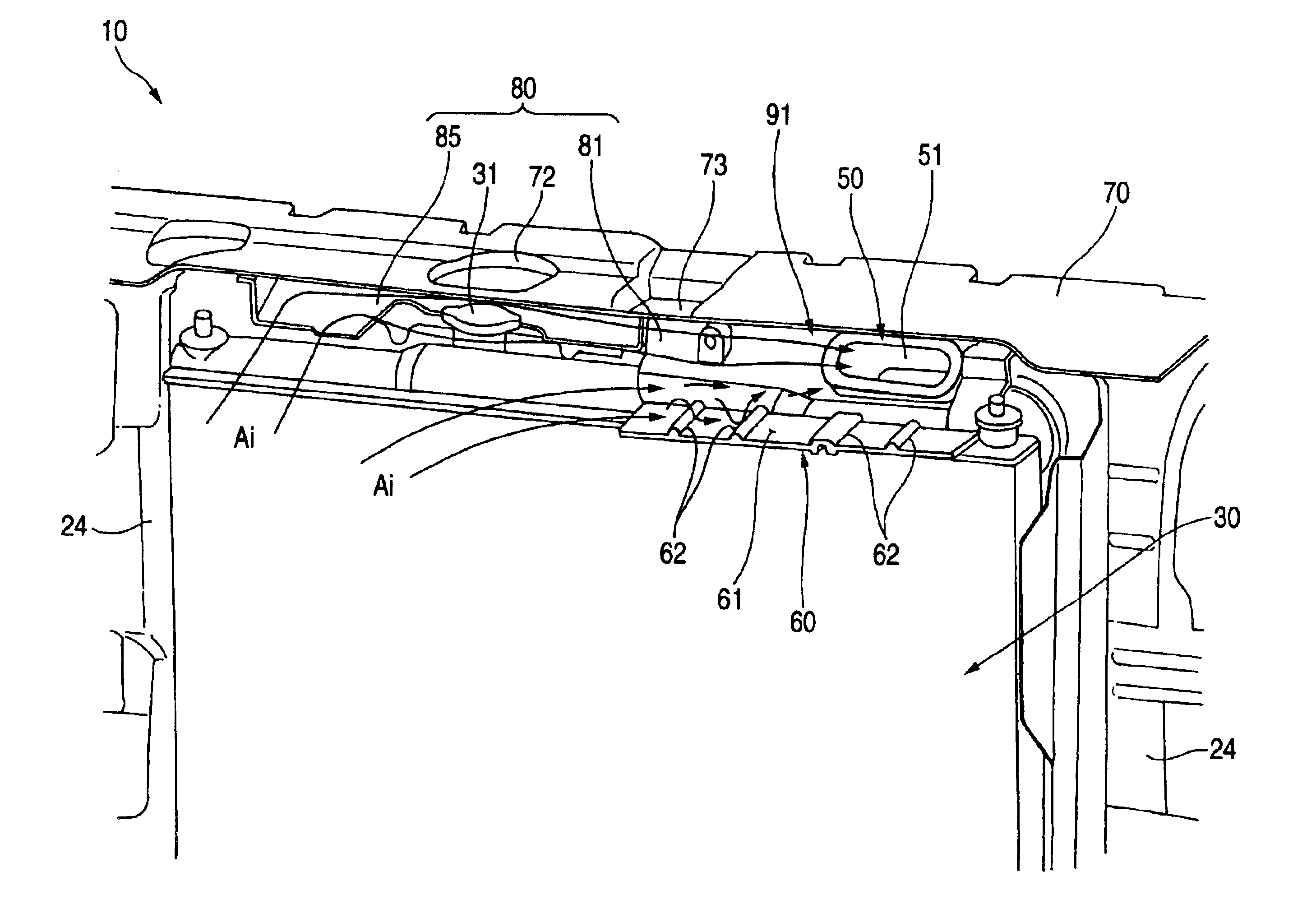
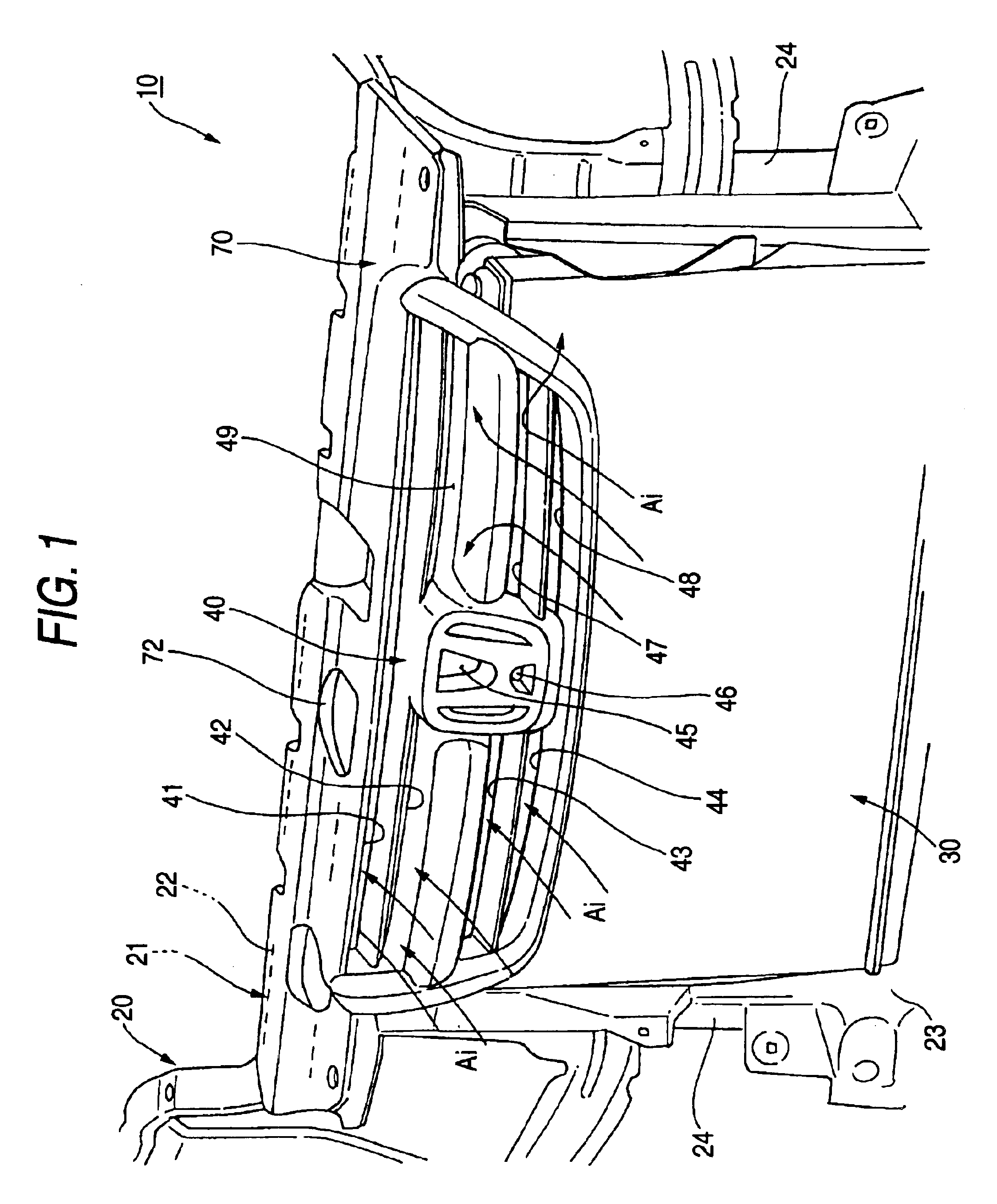
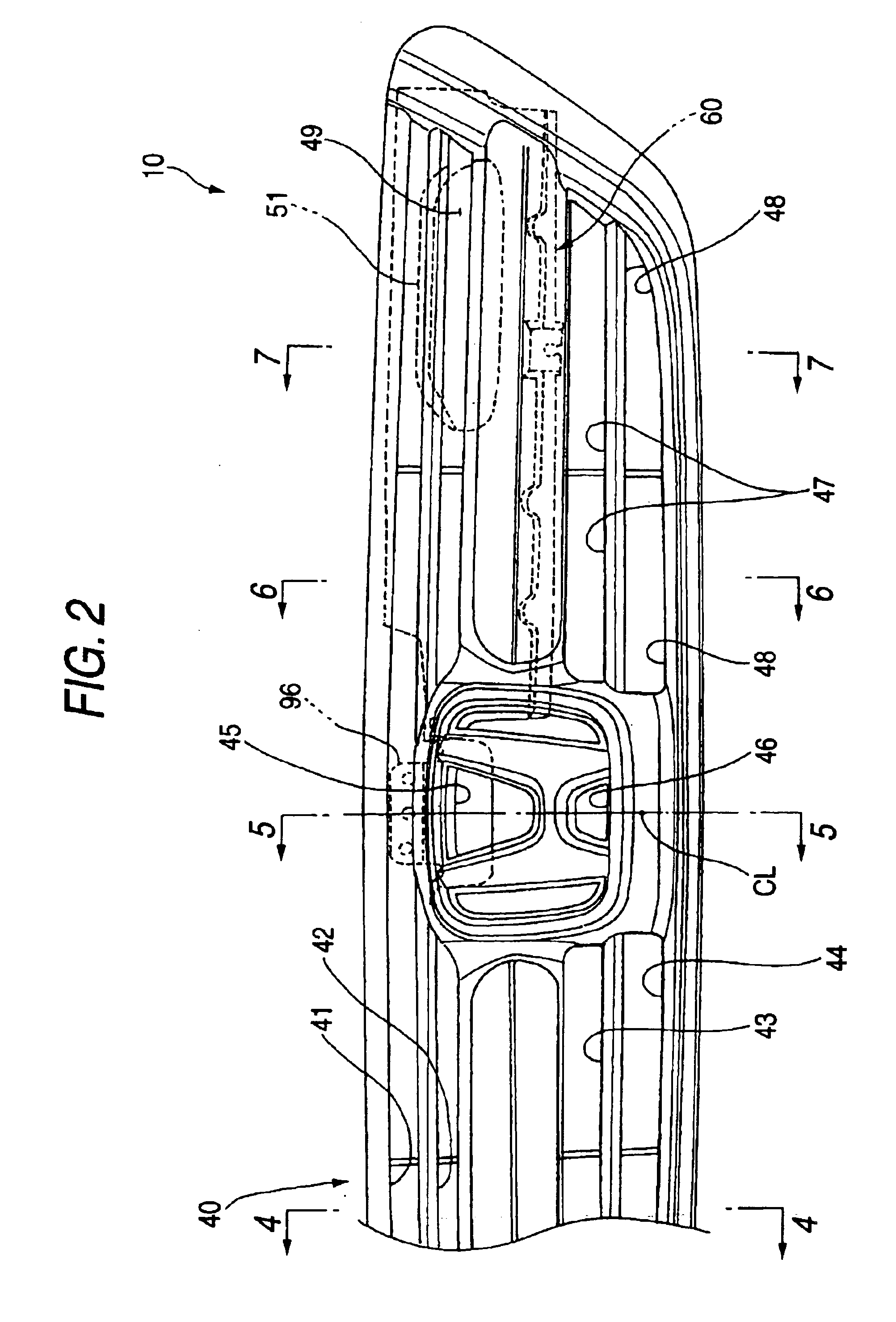
[0031]FIG. 1 is a perspective view (Part 1) of an air-intake structure around a front grille for a vehicle according to the invention in which an engine radiator 30 is disposed at a front part of a vehicle 10 and at a transverse center of the vehicle 10, and a front of the radiator 30 is covered with a front grille 40, the perspective view representing a view of the structure as viewed from the front. The radiator 30 is disposed in front of a front bulkhead 21, and a running air produced when running the vehicle 10 is designed to be taken in from the front through the front grille 40.

[0032]The front bulkhead 21 is a front member of a body frame 20 and comprises an upper cross member ...


PUM


Abstract

An air-intake structure around a front grille for a vehicle in which an engine radiator is disposed at a front part of the body of a vehicle, and a front of the engine radiator is covered with the front grille. An air-intake port for an engine air-induction duct is disposed above the engine radiator. The air-intake port is offset to the left from a transverse center and is oriented toward the front grille. A closed portion is provided on the front grille which closes the entirety of a portion of the front grille which faces the air-intake port.

Description

BACKGROUND OF THE INVENTION[0001]1. Field of the Invention[0002]The present invention relates to an air-intake structure around a front grille for a vehicle.[0003]2. Description of the Related Art[0004]Various types of air-intake structures have been put into practice in which a running air taken through a front grille at the front part of a vehicle is inducted to an engine air cleaner through an intake air duct, and for example, an “Air-intake structure for an intake air duct for a vehicle” is known in JP-A-5-34019U (hereinafter, referred to as “prior art”).[0005]As shown in FIGS. 8 and 9, the prior art is constructed such that a shroud upper 103 as a cross member is provided at a front part of a vehicle body, a radiator 104 is disposed under the shroud upper 103, a transversely elongated horizontal seal board 105 is disposed just in front of the shroud upper 103, and an air-intake port 110 for an air-intake dust 109 for an engine is disposed just behind the shroud upper 103.[0006]...

Claims


Application Information

Patent Timeline
IPC IPC(8): B60K13/00B60K11/00B60K13/02B60K11/08B62D25/08B60R19/52
CPCB60K13/02B60K11/08
Inventor SUWA, TAKAKIOKABE, KOJIROMARUSHIMA, TATSUO
Owner HONDA MOTOR CO LTD
Why Eureka
Try Eureka