Bicycle with shock absorber

a technology of shock absorber and bicycle, which is applied in the direction of friction roller based transmission, steering device, cycle equipment, etc., can solve the problems of rear frame protectors and hangers, bicycle drop is subject to tremendous amounts of stresses and forces, and bicycles are subject to enormous stress and forces

Inactive Publication Date: 2005-04-19
SCHONFELD CARL W
View PDF12 Cites 30 Cited by
  • Summary
  • Abstract
  • Description
  • Claims
  • Application Information

AI Technical Summary

Problems solved by technology

The bicycle drop is subject to tremendous amounts of stresses and forces.
Because the drop is fused to the rear portion of the bicycle, the entire rear portion of the frame would need to be replaced if the drop is damaged.
However, current drop protectors and hangers only protect the outside of the bicycle drop.
Moreover, current drop protectors are screwed into the side of the drop, requiring significant time, effort and tools to replace.
In addition, current drop protectors do not create a clamping action on the drop when the rear wheel axle is tightened to the rear drop.

Method used


Image

  • Bicycle with shock absorber
  • Bicycle with shock absorber
  • Bicycle with shock absorber

Examples


first preferred embodiment

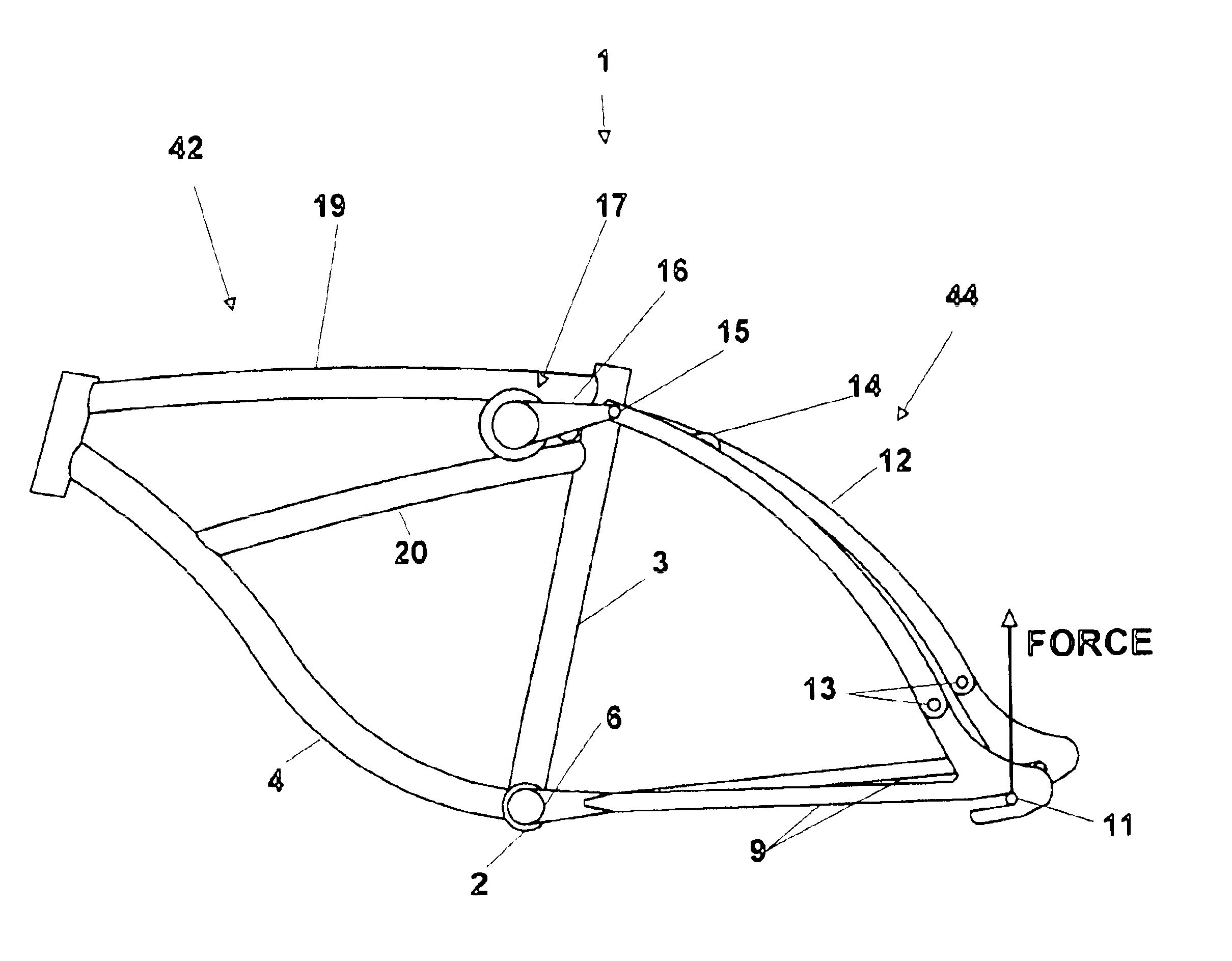
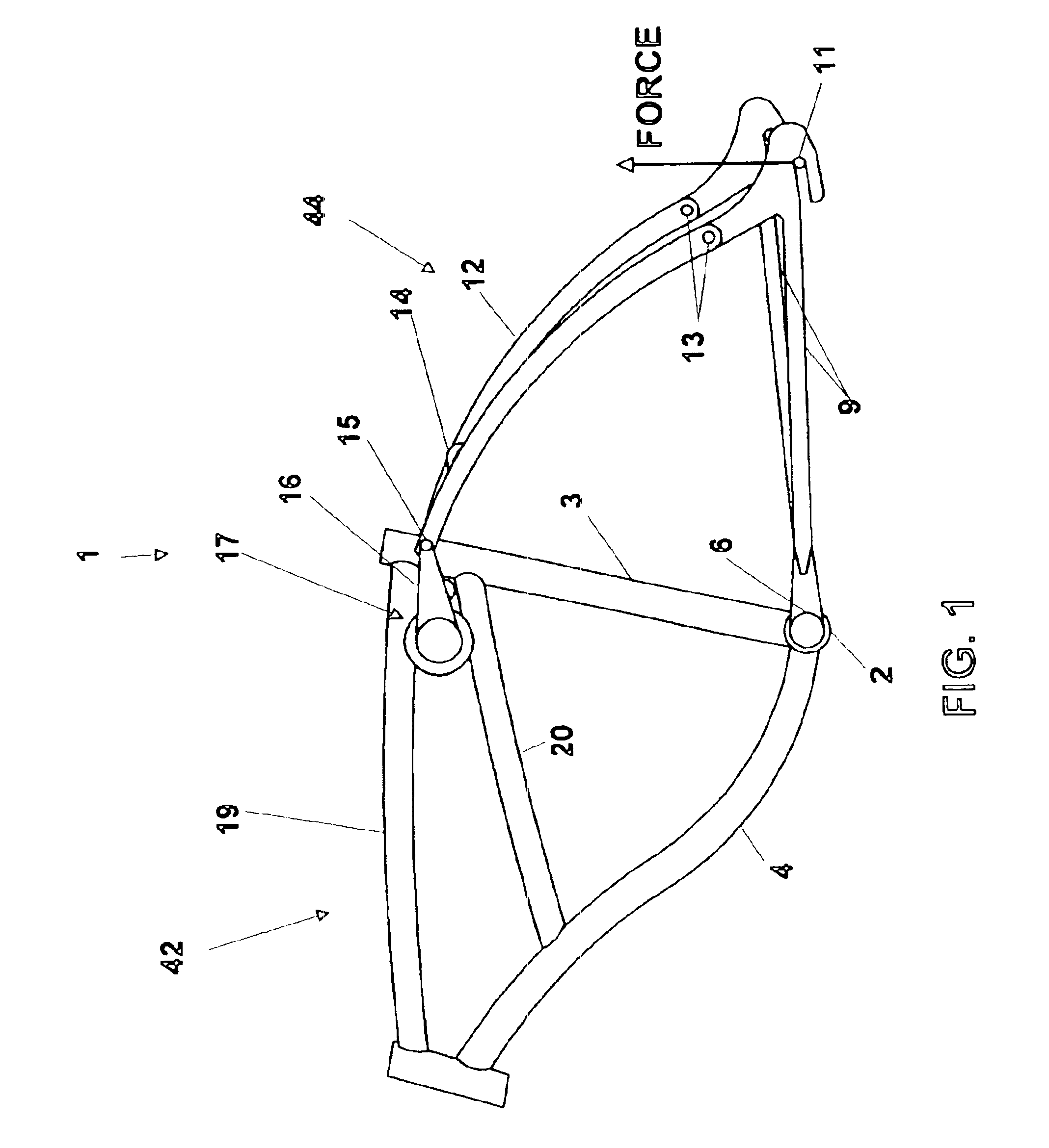
[0040]The present invention may be utilized with most pre-existing bicycle frames. However, for the preferred embodiment, a cruiser type frame was modified. The frame of the cruiser bicycle is shown as bicycle frame 1 in FIG. 1. The procedures for modifying a bicycle to accept the present invention and the use of the present invention are listed below.

Concentric Relative Rotation Bottom Bracket Pivot

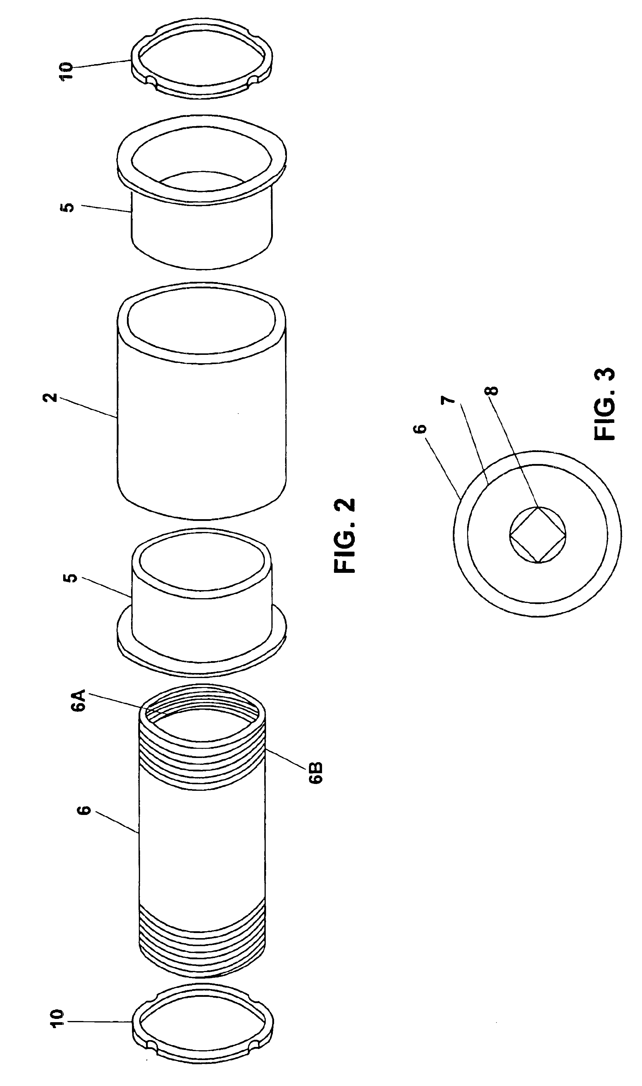
[0041]Aluminum bottom bracket housing 2 is welded to bicycle frame 1 at the intersection of seat support tube 3 and down tube 4, as shown in FIG. 1. The elements that comprise the bottom bracket pivot assembly are illustrated in FIG. 2. Sleeve bearing 5 is a dry, self-lubricating plastic bearing. Sleeve bearing 5 press fits into aluminum bottom bracket housing 2. Aluminum bottom bracket shell 6 slips freely inside both sleeve bearings 5 so as to rotate on sleeve bearings 5. Bottom bracket shell 6 has internal threads 6A so that bearing casings 7 can be threaded onto both sides of bottom ...

second preferred embodiment

Rubber Torsion Shock Absorber—with Hysteresis Damping

[0052]A second preferred embodiment utilizes hysteresis damping to dampen the motion of torsion spring 50. Hysteresis damping as applied to a spring is where spring energy is dissipated through the deformation of a resilient, substantially solid state damping material. In a preferred embodiment of the present invention, the substantially solid state material is rubber.

[0053]A second embodiment of torsion spring assembly 17 is made by substituting the elements described in FIG. 6E (i.e., plastic friction washers 25) with elements described in FIGS. 8A and 8B. Instead of placing plastic friction washers 25 between torsion arms 16 and outer housing 18B, components are inserted to add a damping effect to the torsional motion resisted by torsion spring 50. As seen in FIG. 8B, outer housing 18B has key cutout 18C. Elastomer plate 26 is made out of a high loss factor rubbery substance. Metal elastomer backing plate 26A is cut to fit at k...

second embodiment

Installing Second Embodiment

[0054]All procedures of installing the second embodiment are identical to that of the first embodiment through the installation of actuation shafts 23. Elastomer plates 26 are bonded to elastomer backing plates 26A, which are then keyed to key cutout 18C of outer housing 18B. Rolling indentors 28 are then placed against rolling indentor retainers 27 and both are slid over actuation shafts 23 and pressed against elastomer plates 26. Torsion arms 16 are then slid over shafts 23 and the entire assembly is tightened with bolt 24 and nut 24A as described above under the first embodiment.

Operation of the Damper

[0055]As torsion arms 16 cause actuation shafts 23 to rotate, indentor retainers 27 rotate as well. However, elastomer plates 26 remain essentially stationary because they are keyed to key cutout 18C of outer housing 18B. Between rotating elastomer plates 26 and indentor retainers 27 are rolling indentors 28. As indentor retainers 27 rotate around shafts ...


PUM


Abstract

A bicycle with a torsional shock absorber comprised of a torsion spring assembly. The elements of the torsion spring assembly include: housing, a shaft positioned within the housing, a rubbery substance positioned between the interior surface of the housing and the outer surface of the shaft, and a damper. The torsional shock absorber is mounted on the bicycle such that shock forces are converted into rotational forces tending to rotate the shaft within the housing. These rotational forces are resisted by the spring force created by the rubbery substance within the torsion spring assembly; thereby absorbing the shock forces. In a preferred embodiment, the rubbery substance is bonded to the interior surface of the housing and the outer surface of the shaft. In a preferred embodiment, the front and rear portions of the bicycle frame pivot about the pedal spindle axis. Also, in a preferred embodiment, the housing of the torsion spring assembly is rigidly connected to the front portion of the bicycle frame in-between the top tube and middle brace and just in front of the seat tube. The rear portion of the bicycle frame is pivotally connected to two torsion arms rigidly connected to the shaft.

Description

[0001]This invention relates to bicycles, and more specifically to bicycles with shock absorbers. This application is a continuation-in-part of Ser. No. 09 / 431,878 filed Nov. 2, 1999 (which issued as U.S. Pat. No. 6,386.567 on May. 14, 2002), which is a continuation-in-pan of Ser. No. 09 / 049,266 filed Mar. 27, 1998 (which issued as U.S. Pat. No. 5,975,550 on Nov. 2, 1999).BACKGROUND OF THE INVENTION[0002]Bicycles have been used as a means of recreation and transportation for many years. With the advent of the fuel crisis in the 1970's and the rise in overall health consciousness in society, bicycling recently gained even greater popularity. Finally, just recently, mountain biking has become the most popular form of bicycling with sales of mountain bikes surpassing those of ordinary road bikes.[0003]With the increase in the popularity of mountain biking, bicycle developers have been faced with issues that were of little or no concern when most bicycle riders road on the street. Forem...

Claims


Application Information

Patent Timeline
Patent Type & Authority Patents(United States)
IPC IPC(8): B62K17/00B62K25/28B62K25/04F16F1/02F16F1/14
CPCB62K17/00F16F1/14B62K25/28
Inventor SCHONFELD, CARL W.
Owner SCHONFELD CARL W
Why Eureka
Try Eureka