Harvester combine

a combine and harvester technology, applied in the field of combine harvesters, can solve the problems of serious fire hazards, difficult, or even impossible, and a serious hazard to engine operation

Inactive Publication Date: 2005-04-19
REKORDVERKEN SWEDEN
View PDF10 Cites 36 Cited by
  • Summary
  • Abstract
  • Description
  • Claims
  • Application Information

AI Technical Summary

Benefits of technology

[0012]The principal object of the invention is to provide a combine harvester that does not suffer from the drawbacks and disadvantages outlined above.

Problems solved by technology

In threshing, large amounts of dust and clouds of particles generate in the area around the harvester, posing a considerable hazard to the engine operation and above all being a serious fire hazard.
For various reasons, such as lack of space or because of different structural / functional solutions, it is very difficult, or even impossible, in some types of combine harvesters, to mount the husk discharge device in a manner allowing the husk without problems to be mixed with or be blown into the straw that is to be chopped in the straw chopping device upstream from said device.
In addition, particularly in the case of large volumes of husks (and boss) it may sometimes involve difficulties to satisfactorily and without unnecessary waste blow the husk out through the open through-passage in the guide plate and into the straw chopping device.
Furthermore, owing to the admixture of husk into the straw that is to be chopped, upstream from the straw chopping device, it may sometimes happen, for instance when large volumes of straw and husk are to be processed or when their moisture contents are high, that the straw chopping device is “overloaded” or becomes clogged.
In turn, this situation may lead to impaired spreading of the chopped straw together with the likewise at least to some extent chopped, and even to breakdown.

Method used


Image

  • Harvester combine
  • Harvester combine
  • Harvester combine

Examples


Embodiment Construction

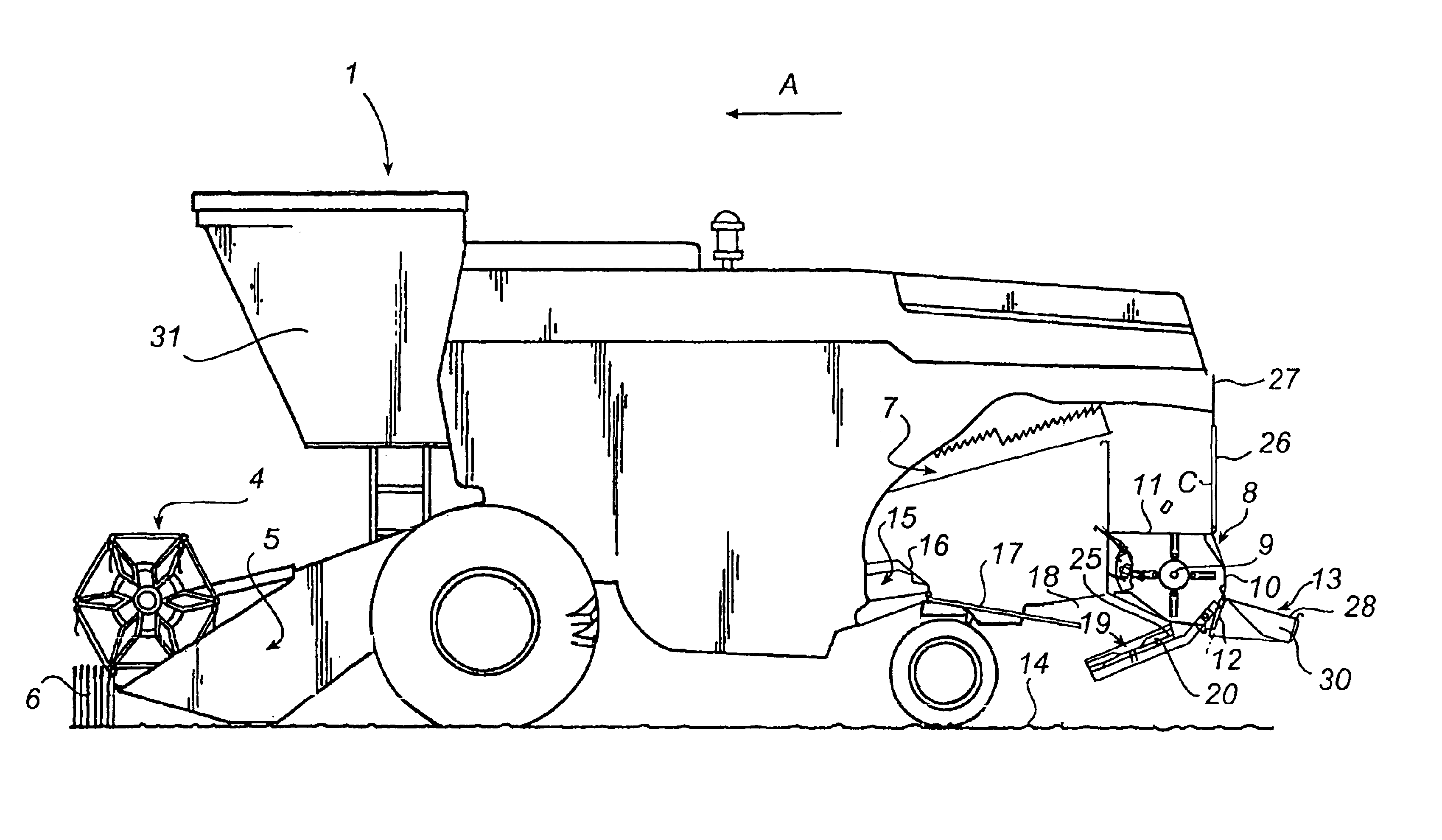
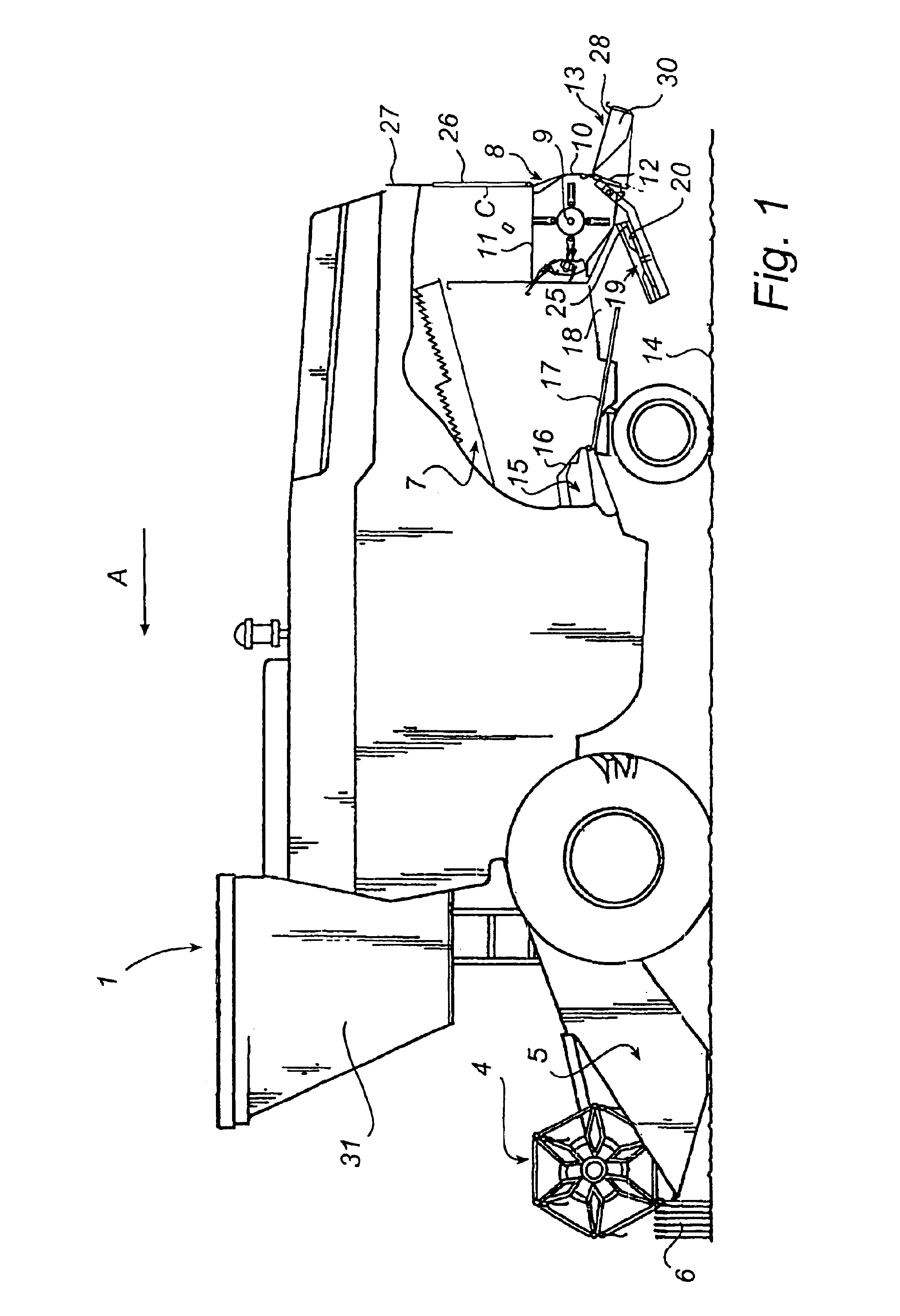
[0029]The combine harvester designated generally in the drawings by numeral reference 1 is, with the exception of the devices for processing husks 2 and straw 3 to be described in closer detail further on, of essentially conventional design comprising a pick-up reel 4 and a cutting table 5, the width of which considerably exceeds that of the harvester 1. The crop, in the present case straw fodder plants 6 or the like that are to be harvested, is cut off on the cutting table 5 and is transported via conveyors or the like, not shown, to a thresher, not shown either, where the straw 3 and the grains, not shown, are separated from each other.

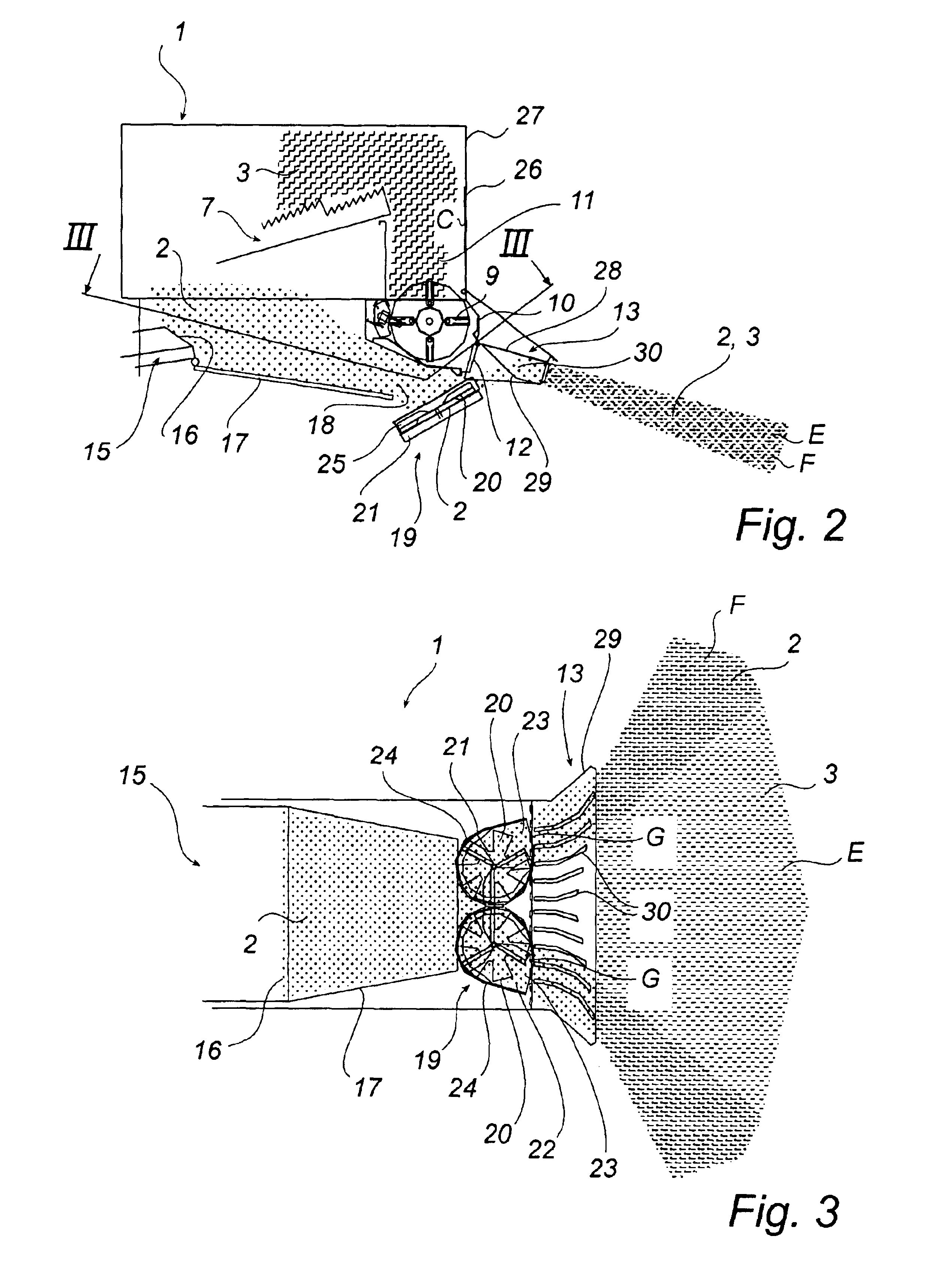
[0030]The straw 3 continues via a straw shaking unit, generally designated by numeral 7, or alternatively via a threshing cylinder or the like, not shown, to a straw chopping device, which is located at the rear end of the harvester 1 as seen in the direction of advancement A and designated generally by numeral 8. This straw chopping device 8 thus i...


PUM


Abstract

A combine harvester has a husk discharge device mounted downstream from a sieving unit, and a blower mounted in a housing having at least one husk discharge opening, and a straw chopping device, which is located downstream from a straw shaking device and the husk discharge device and which has a rotary cutter mounted in a housing to chop the straw, the housing having an inlet for the unchopped straw and an outlet for the chopped straw. A guide means is located upstream of the straw chopping device, the guide means being displaceable between a first position for closing the inlet so as to effect bypassing of the straw chopping device and allowing deposition of the unchopped straw in the form of strings, and a second position in which is exposed the inlet to allow chopping of straw. A spreading device for spreading of the chopped straw received from the straw chopping device is connected to the outlet thereof and is formed with spreader wings. The husk discharge opening is arranged to be directed towards the spreading device, allowing husks to be blown into the device and spreading of the husks over the ground with the aid of the spreader wings.

Description

TECHNICAL FIELD OF INVENTION[0001]The present invention relates generally to a combine harvester comprising a husk discharge device equipped with at least one blower disposed inside a housing having at least one husk discharge opening, a straw chopping device having an inlet for intake of chopped straw and an outlet for discharge of the chopped straw, and a spreading device having an outlet, which is connected to the straw-chopper outlet and formed with spreader wings.[0002]More precisely, the invention relates to a combine harvester comprising a device for discharge of husks and chaff received from a sieving unit mounted on the combine harvester, said husk discharge device being located downstream from the sieving unit and formed with at least one blower, which is rotationally mounted in a housing having at least one husk discharge opening, a device for chopping straw received from a straw shaking unit or threshing cylinder mounted on the combine harvester, said straw chopping devi...

Claims


Application Information

Patent Timeline
Patent Type & Authority Patents(United States)
IPC IPC(8): A01D41/00A01D41/12
CPCA01D41/1243Y10S460/901
Inventor HOLMEN, BENGT
Owner REKORDVERKEN SWEDEN
Why Eureka
Try Eureka