Unipolar transverse flux machine

a technology of unipolar transversal and flux machine, which is applied in the direction of magnetism circuit shape/form/construction, instruments, horology, etc., can solve the problems of single-strand machine with only one rotor module and stator module, and cannot start by itsel

Inactive Publication Date: 2005-04-19
ROBERT BOSCH GMBH
View PDF10 Cites 55 Cited by
  • Summary
  • Abstract
  • Description
  • Claims
  • Application Information

AI Technical Summary

Benefits of technology

[0007]The unipolar transverse flux machine according to the invention has the advantage of an extremely flat design and a definite start in a particular direction, which is assured by the two-strand design of the stator.

Problems solved by technology

The single-strand machine with only one rotor module and stator module has the disadvantage that it cannot start by itself and additional auxiliary measures must be provided for starting it.

Method used


Image

  • Unipolar transverse flux machine
  • Unipolar transverse flux machine
  • Unipolar transverse flux machine

Examples


Embodiment Construction

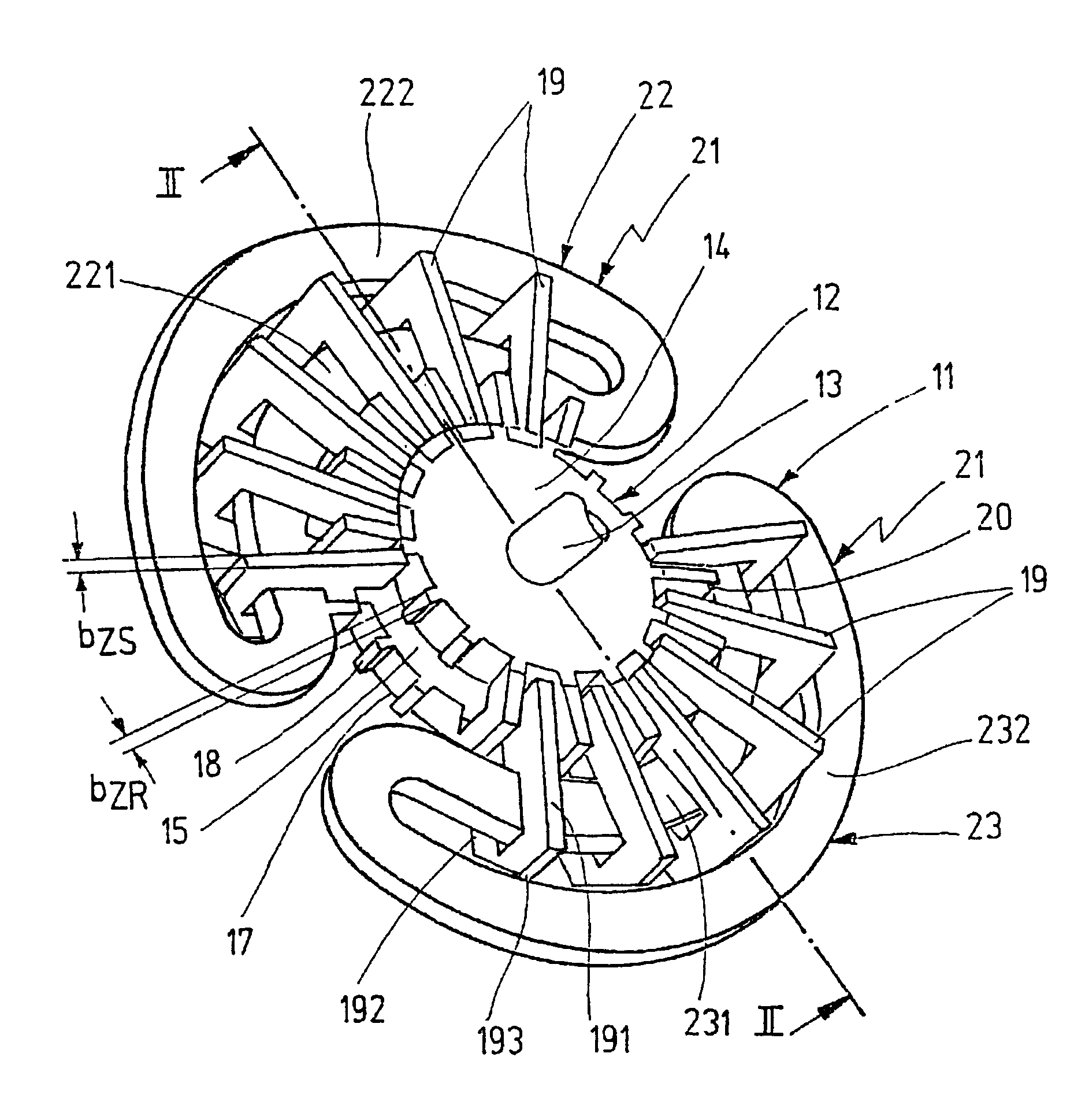
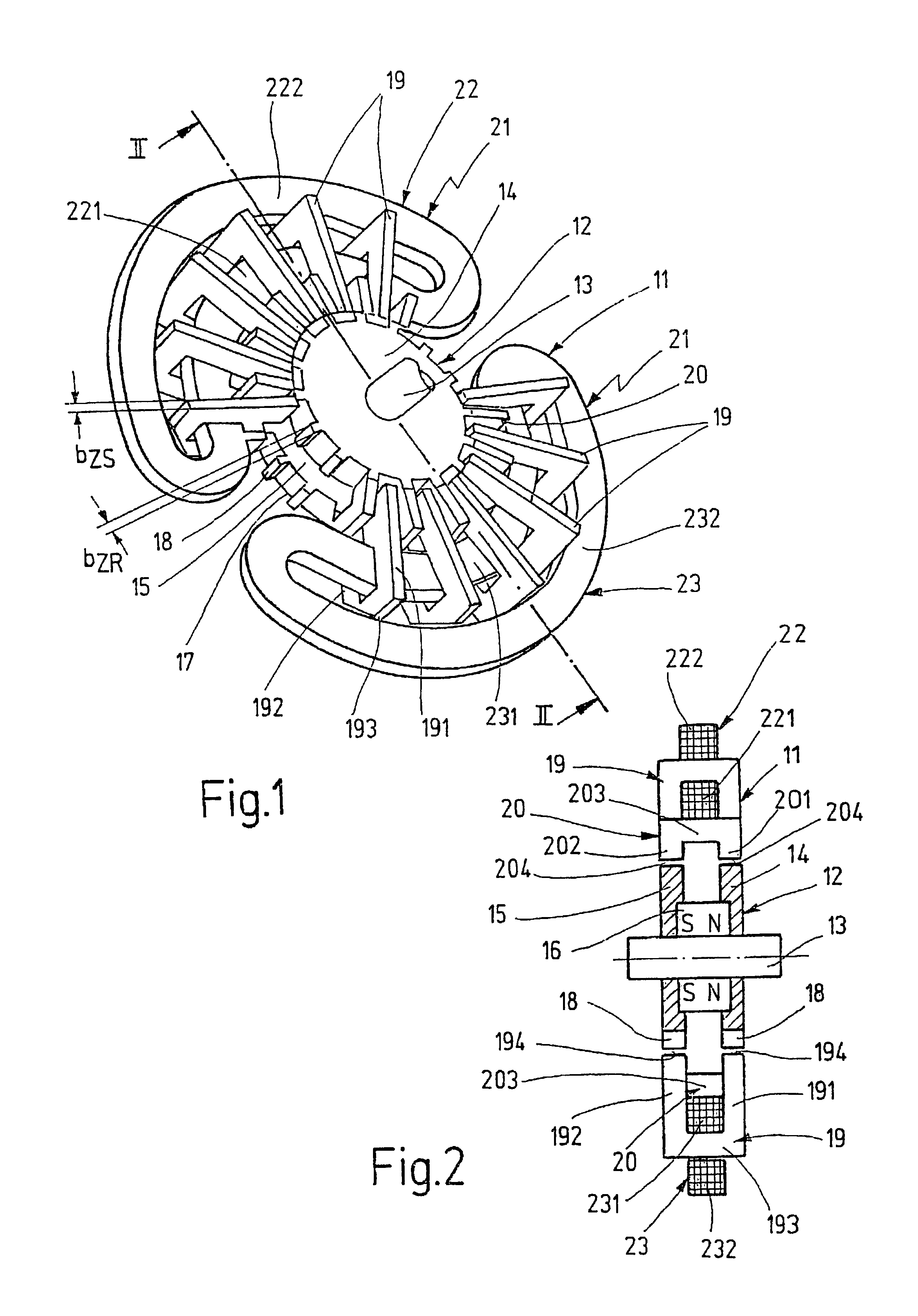
[0012]The unipolar transverse flux motor shown in various views and sections in the drawings as an exemplary embodiment of a universal unipolar transverse flux machine has a stator 11 and a rotor 12, which rotates inside the stator 11 and is non-rotatably supported on a rotor shaft 13.

[0013]The rotor 12 is comprised of two coaxial ferromagnetic rotor rings 14, 15 (FIG. 2), which are non-rotatably supported on the rotor shaft 13 and between themselves, clamp a permanent magnet ring 16, which is magnetized in a unipolar fashion in the axial direction, i.e. in the direction of the rotor axis or housing axis. In FIG. 2, the direction of the magnetization of the permanent magnet ring 16 is labeled N-S by way of example. Each rotor ring 14, 15 is provided with a constant tooth spacing on its outer circumference oriented away from the rotor shaft 13 so that the teeth 18, which are separated from one another by respective tooth spaces 17, of the tooth rows produced have a uniform rotation a...


PUM


Abstract

In a unipolar transverse flux machine, in particular a motor, having a rotor, which is comprised of two coaxial, ferromagnetic, toothed rotor rings, and a permanent magnet ring, which is magnetized in an axially unipolar fashion and is clamped axially between these rotor rings, and having a stator, which is concentric to the rotor shaft and has U-shaped stator yokes that represent the magnet poles, yoke elements, and a stator winding, in order to achieve an extremely flat design and to assure a definite start in a particular direction, the stator winding is embodied with two coils, whose one coil side extends respectively over a group of stator yokes and yoke elements arranged in succession in the circumference direction, along the side of the yoke elements remote from the rotor shaft, between the yoke legs, where the group spanned by the coil side of the one coil is disposed spatially offset on the stator circumference and electrically offset by 90° in relation to the group spanned by the coil side of the other coil.

Description

CROSS-REFERENCE TO RELATED APPLICATIONS[0001]This application is a 35 USC 371 application of PCT / DE 01 / 02668 filed on Jul. 17, 2001.BACKGROUND OF THE INVENTION[0002]1. Field of the Invention[0003]The invention is directed to an improved unipolar transversal flux machine.[0004]2. Description of the Prior Art[0005]In a unipolar transverse flux machine of this kind (DE 100 21 914.4), it has already been proposed to embody the stator winding as an annular coil, which is disposed coaxial to the rotor axis and which, on the outside of the yoke elements remote from the rotor axis, passes through the yoke legs of the stator yoke. As a result, the machine can be one-stranded, i.e. can be embodied with one stator module and one rotor module, or can be multi-stranded, with at least two stator modules and rotor modules, where each of the stator modules disposed axially adjacent to each other has an annular coil of this kind. In the two-strand design, the stator modules or rotor modules are disp...

Claims


Application Information

Patent Timeline
Patent Type & Authority Patents(United States)
IPC IPC(8): H02K21/14H02K21/18
CPCH02K21/14H02K2201/12H02K21/18
Inventor KASTINGER, GUENTER
Owner ROBERT BOSCH GMBH
Why Eureka
Try Eureka