Headlamp for vehicle

Inactive Publication Date: 2005-04-19
KOITO MFG CO LTD
View PDF11 Cites 54 Cited by
  • Summary
  • Abstract
  • Description
  • Claims
  • Application Information

AI Technical Summary

Benefits of technology

[0025]More specifically, a position in which the light distribution pattern for a low beam is to be formed is generally regulated on the basis of the position of a cutoff line. If the cutoff line forming unit is provided in the middle stage, therefor

Problems solved by technology

However, it is hard to form a light distribution pattern with a desirable luminous intensity distribution.
Therefore, there is a problem in that the light distribution pattern of the headlamp for a vehicle which is obtained as a synthetic light distribution pattern

Method used


Image

  • Headlamp for vehicle
  • Headlamp for vehicle
  • Headlamp for vehicle

Examples


Embodiment Construction

[0038]An embodiment of the invention will be described below with reference to the drawings.

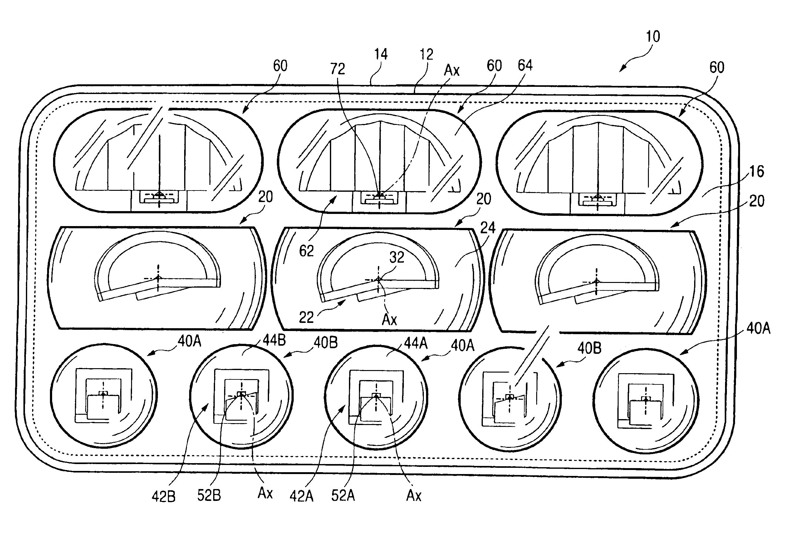
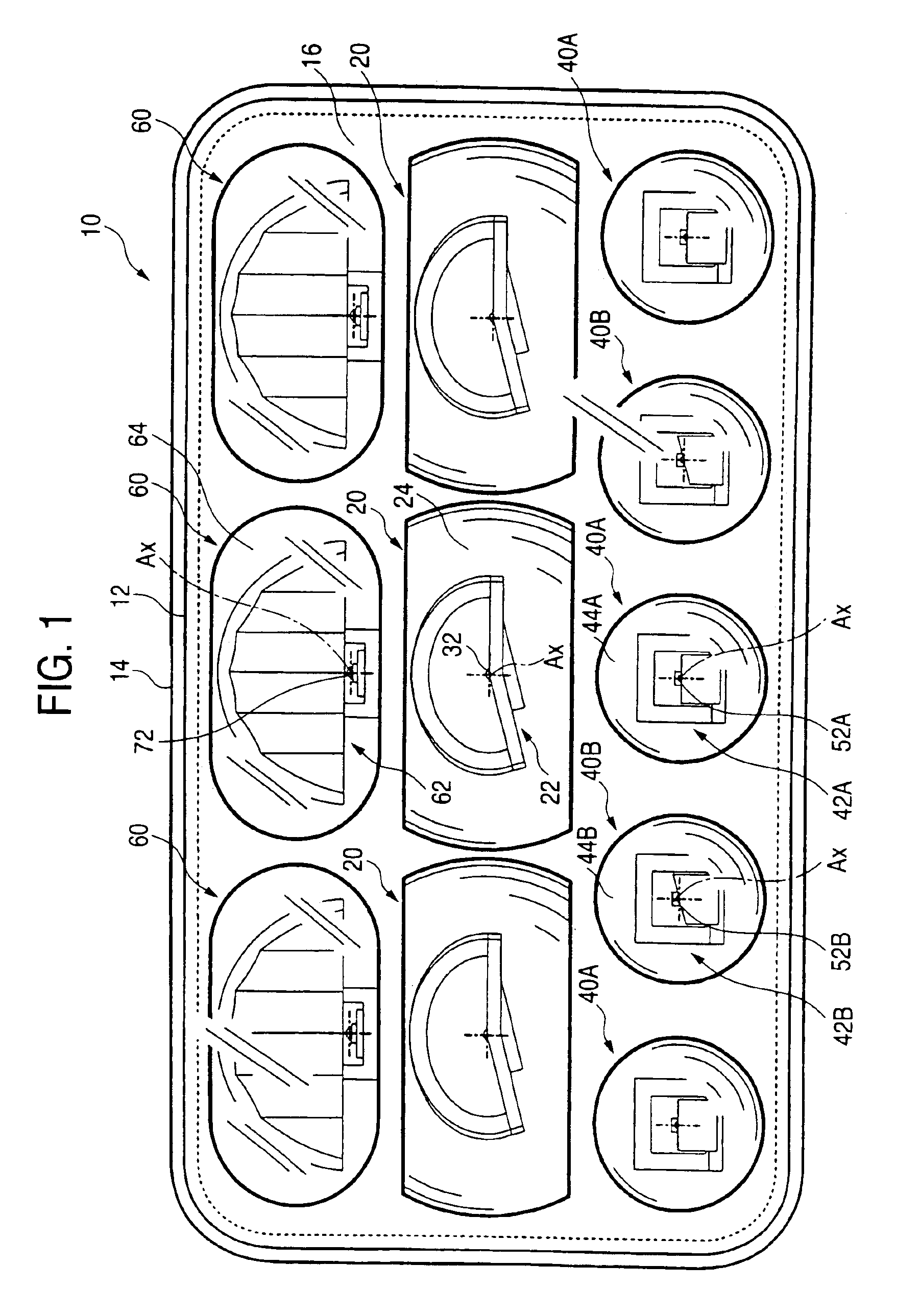
[0039]FIG. 1 is a front view showing a headlamp 10 for a vehicle according to an embodiment of the invention.

[0040]The headlamp 10 for a vehicle is a headlamp for a low beam and has such a structure that eleven lighting units 20, 40A, 40B and 60 are accommodated in three upper and lower stages in a lamp housing formed by a plain translucent cover 12 and a lamp body 14.

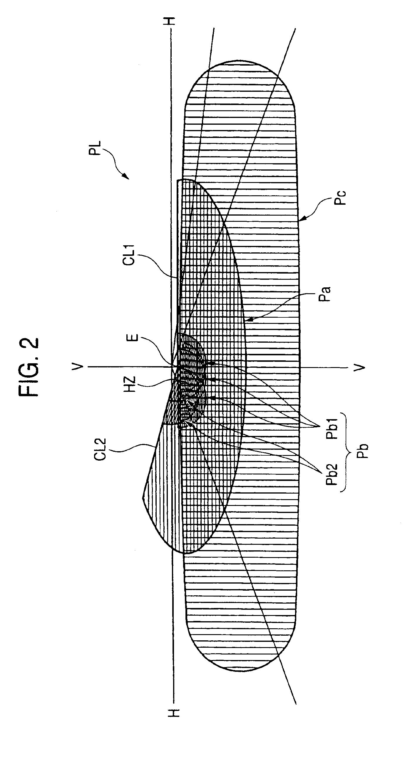
[0041]FIG. 2 is a perspective view showing a light distribution pattern PL for a low beam which is formed on a virtual vertical screen provided in a forward position of 25 m from a lighting unit by a light irradiated forward from the headlamp 10 for a vehicle.

[0042]The light distribution pattern PL for a low beam is a left light distribution pattern having horizontal and oblique cutoff lines CL1 and CL2 on an upper edge thereof, and the position of an elbow point E to be an intersection of both of the cutoff lines is set into a ...


PUM


Abstract

A headlamp having a plurality of lighting units using light emitting diodes as light sources. A cutoff line forming unit, hot zone forming units, and a diffusion region forming unit are used as these lighting units. Consequently, a light distribution pattern for a low beam having a desirable pattern shape and light intensity distribution can be obtained as the synthetic light distribution pattern of light distribution patterns formed by the irradiation of a light from these three kinds of lighting units.

Description

BACKGROUND OF THE INVENTION[0001]1. Technical Field to which the Invention Belongs[0002]The present invention relates to a headlamp for a vehicle that is constituted to form a light distribution pattern for a low beam using a plurality of semiconductor light emitting elements as light sources.[0003]2. Description of the Related Art[0004]In a marker lamp for a vehicle such as a tail lamp, a light emitting diode is often used as the light source. For example, JP-A-2002-50214 describes a marker lamp for a vehicle in which a plurality of lighting units using light emitting diodes to be light sources are arranged.[0005]In addition, JP-A-2001-266620 describes a headlamp for a vehicle which has such a structure such that a part of a plurality of light emitting diodes arranged in a matrix is selectively turned on to form a desirable light distribution pattern.[0006]In the structure of the lighting unit described in JP-A-2001-266620, it is possible to change the shape of a light distribution...

Claims


Application Information

Patent Timeline
IPC IPC(8): B60Q1/04F21V7/00F21S8/10F21S8/12F21V13/00F21W101/10F21Y101/02
CPCB60Q1/04F21S48/1154F21S48/137F21S48/1159Y10S362/80F21Y2101/02F21Y2115/10F21S41/143F21S41/148F21S41/153F21S41/336F21S41/20F21S41/32F21W2102/00
Inventor ISHIDA, HIROYUKISAZUKA, KIYOSHITATSUKAWA, MASASHI
Owner KOITO MFG CO LTD
Why Eureka
Try Eureka