Duty cycle corrector

a technology of duty cycle and corrector, which is applied in the direction of generating/distributing signals, pulse techniques, instruments, etc., can solve the problems of clock signals not arriving at various logic elements as expected, high low times of a signal may not always be equal

Inactive Publication Date: 2005-04-19
ORACLE INT CORP
View PDF24 Cites 32 Cited by
  • Summary
  • Abstract
  • Description
  • Claims
  • Application Information

AI Technical Summary

Problems solved by technology

However, due to one or more types of variations in fabrication, temperature, and voltage, clock signals may not arrive at various logic elements

Method used


Image

  • Duty cycle corrector
  • Duty cycle corrector
  • Duty cycle corrector

Examples


Embodiment Construction

[0023]Specific embodiments of the invention will now be described in detail with references to the accompanying figures. Like elements in the various figures are denoted by like reference numerals throughout the figures for consistency.

[0024]In the following detailed description of the invention, numerous specific details are set forth in order to provide a more thorough understanding of the invention. However, it will be apparent to one of ordinary skill in the art that the invention may be practiced without these specific details. In other instances, well-known features have not been described in detail to avoid obscuring the invention.

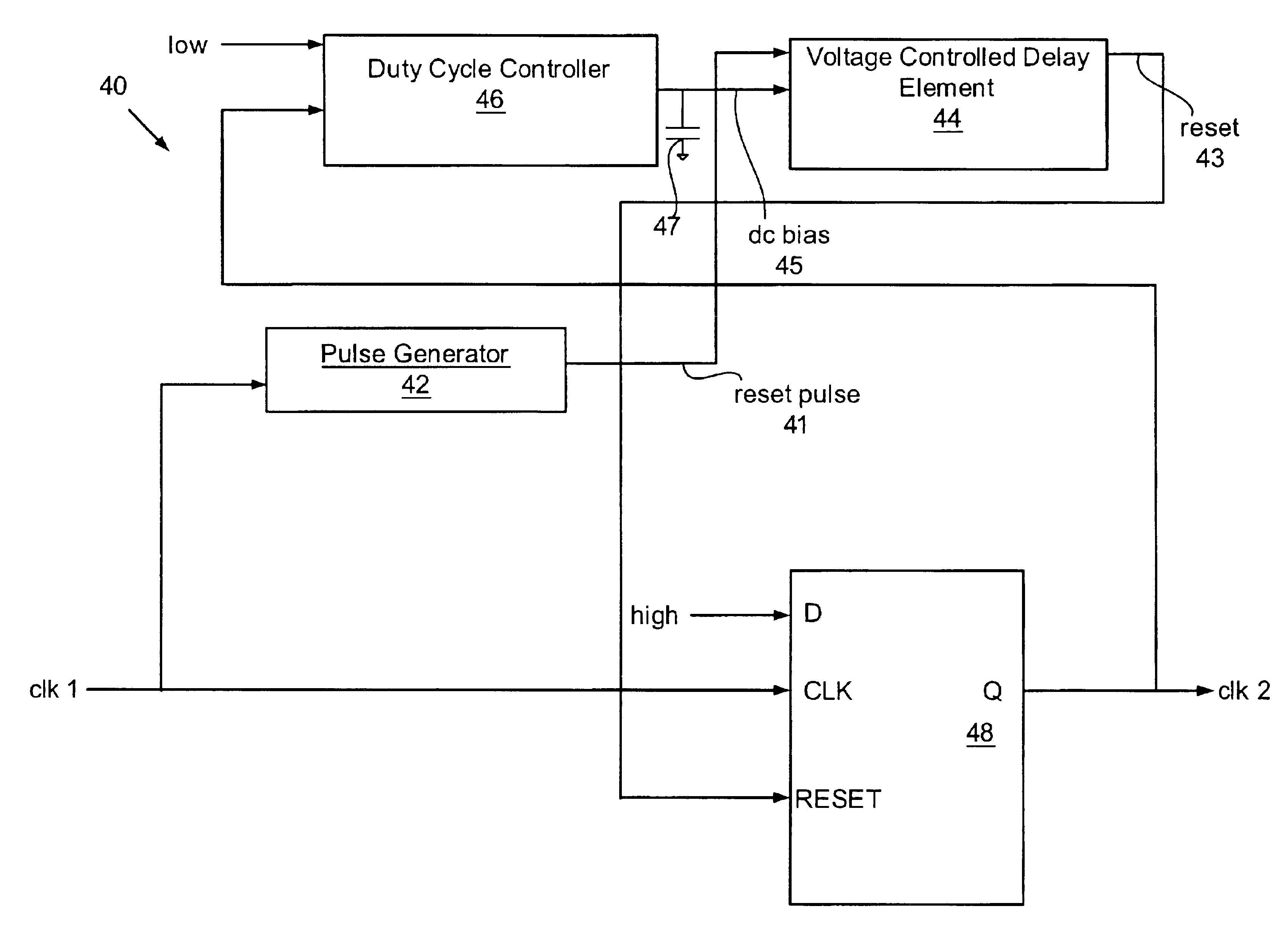
[0025]Embodiments of the invention relate to a method and apparatus for correcting a duty cycle of a clock signal. A duty cycle correction device uses an output clock signal as a feedback input to increase or decrease the high time of the output clock signal. An analog biasing signal is increased or decreased based on the high time of the output clo...


PUM


Abstract

A device that uses an input clock signal to generate an output clock signal with a desired frequency is provided. The device uses a voltage controlled delay element that outputs a reset signal to a flip-flop dependent on a bias signal and the input clock signal. When triggered, the flip-flop outputs a transition on the output clock signal, which, in turn, serves as an input to a duty cycle corrector that generates the bias signal dependent on the configuration of the duty cycle corrector. The duty cycle corrector may be configured to generate the bias signal so as to be able to operatively control the duty cycle of the output clock signal.

Description

BACKGROUND OF INVENTION[0001]A typical computer system includes at least a microprocessor and some form of memory. The microprocessor has, among other components, arithmetic, logic, and control circuitry that interpret and execute instructions necessary for the operation and use of the computer system. FIG. 1 shows a typical computer system (10) having a microprocessor (12), memory (14), integrated circuits (16) that have various functionalities, and communication paths (18, 20), i.e., buses and wires, that are necessary for the transfer of data among the aforementioned components of the computer system (10).[0002]A clock signal is critical to the operation of a microprocessor-based computer system. The clock signal initiates and synchronizes the operation of almost all of the components of the typical computer system. As computers operate at increasing clock speeds, it becomes critical to ensure that clock signals on a microprocessor are provided to various logic elements on the mi...

Claims


Application Information

Patent Timeline
IPC IPC(8): H03K5/156H03K3/00H03K3/017H03K5/00
CPCH03K5/1565H03K2005/00045
Inventor YEE, GINBOBBA, SUDHAKARGAUTHIER, CLAUDELIU, DEANOOI, LYNNTRIVEDI, PRADEEP
Owner ORACLE INT CORP
Why Eureka
Try Eureka