Light emission drive circuit and its drive control method and display unit and its display drive method

a technology of light emission and drive control, which is applied in the direction of electroluminescent light sources, static indicating devices, instruments, etc., can solve the problem of difficulty in stably realizing the light emission operation at the appropriate luminance gradation sequence, and achieve good display image quality

Active Publication Date: 2006-06-15
SOLAS OLED LTD
View PDF7 Cites 148 Cited by
  • Summary
  • Abstract
  • Description
  • Claims
  • Application Information

AI Technical Summary

Benefits of technology

[0021] An object of the present invention is to provide an emission drive circuit capable of realizing the operation for light-emission driving a light emission element at an appropriate luminance gradation sequence in accordance with the display data by supplying a light emission drive current having a current value in accordance with the display data and its drive control method and a display unit having a good display image quality and its display drive method.

Problems solved by technology

For this reason, it becomes difficult to stably realize the light emission operation at the appropriate luminance gradation sequence in accordance with the display data for a long time.

Method used


Image

  • Light emission drive circuit and its drive control method and display unit and its display drive method
  • Light emission drive circuit and its drive control method and display unit and its display drive method
  • Light emission drive circuit and its drive control method and display unit and its display drive method

Examples


Embodiment Construction

[0181] An emission drive circuit and its drive control method and a display unit and its display drive method according to the invention will be described in detail below with reference to the embodiment. First, the emission drive circuit and its drive control method according to the invention will be described with reference to the drawings below.

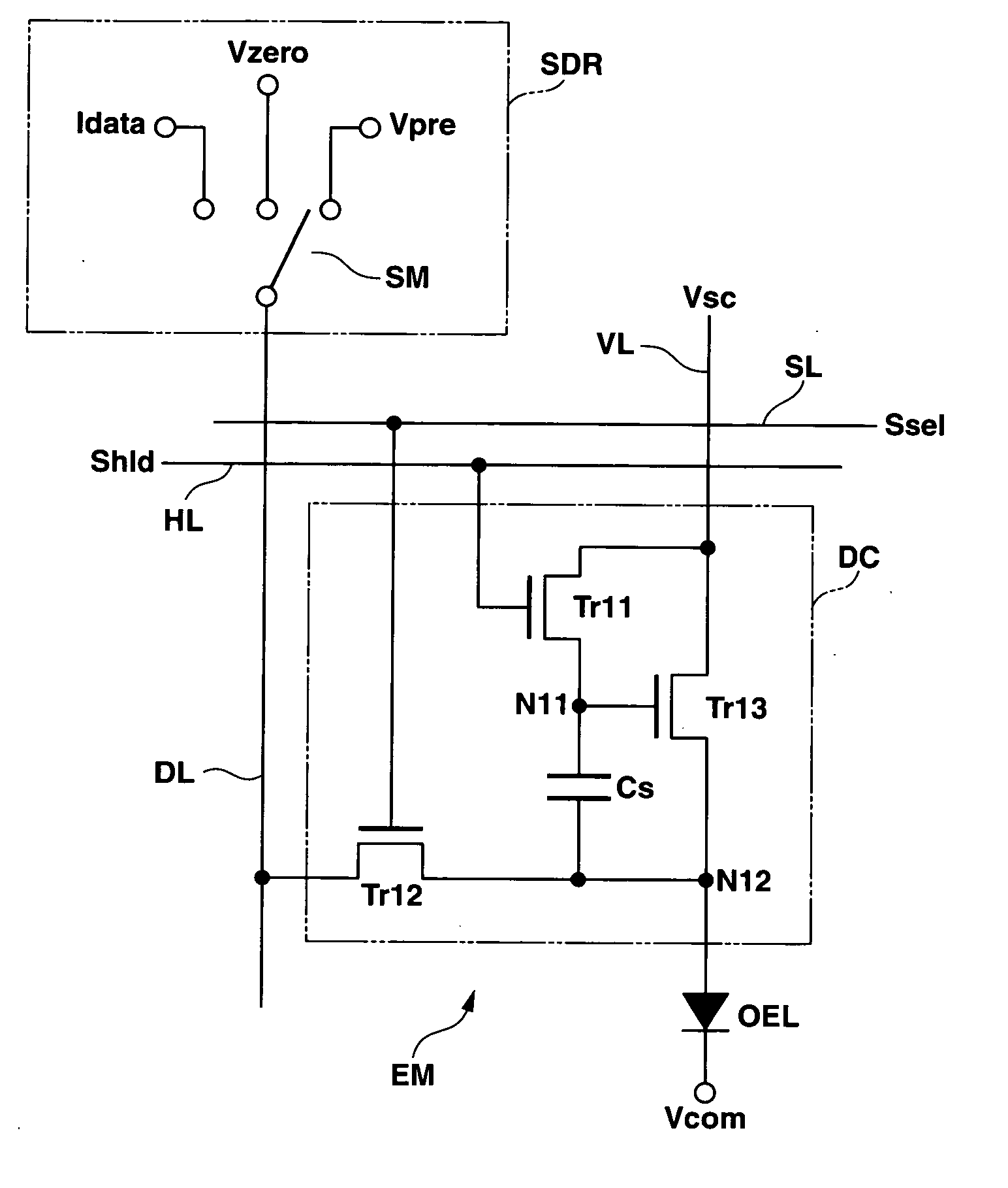
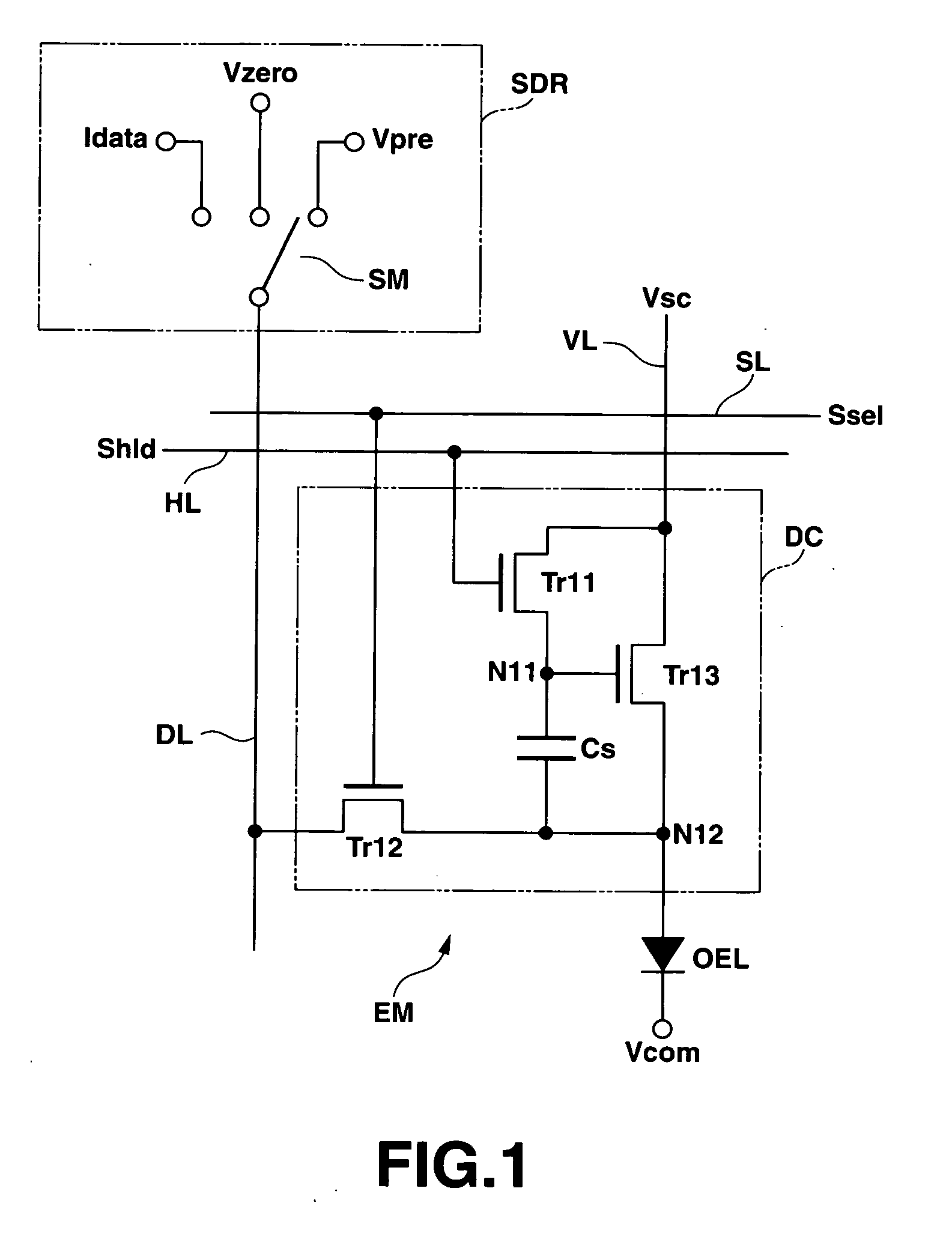
[0182]FIG. 1 is a circuit block diagram showing an embodiment of a light emission drive circuit according to the invention.

[0183] As shown in FIG. 1, for example, a light emission drive circuit DC according to the invention is configured so as to have: a selection transistor (writing control means) Tr 12 configured by a thin film transistor located in the vicinity of each intersecting point of a plurality of selection lines SL and a plurality of data lines DL arranged so as to be at right angles to each other, in which a gate terminal (a control terminal) is connected to a selection line SL and a source terminal and a drain terminal (one...


PUM


Abstract

A light emission drive circuit includes an electric charge accumulating section for accumulating electric charges on the basis of a gradation sequence signal designating a luminance gradation sequence. A light emission control section flows a light emission drive current having a current value in accordance with an amount of the electric charges accumulated in the electric charge accumulating section. A writing control section controls a supplying state of the electric charges based on the gradation sequence signal to the electric charge accumulating section on the basis of a first control signal. A voltage control section controls a drive voltage for operating the light emission controlling section on the basis of a second control signal.

Description

CROSS-REFERENCE TO RELATED APPLICATIONS [0001] This application is based upon and claims the benefit of priority from prior Japanese Patent Applications No. 2004-360105, filed Dec. 13, 2004; No. 2004-368031, filed Dec. 20, 2004; and No. 2004-368850, filed Dec. 21, 2004, the entire contents of all of which are incorporated herein by reference. BACKGROUND OF THE INVENTION [0002] 1. Field of the Invention [0003] The present invention relates to an emission drive circuit and its drive control method and a display unit and its display drive method. Particularly, the present invention relates to a light emission drive circuit that can apply a current control type (or a current drive type) of light emission element emitting light at a predetermined luminance gradation sequence by supplying a current in accordance with the display data to plural display panels (pixel arrays) and its drive control method, and a display unit provided to each display pixel and its display drive method. [0004] ...

Claims


Application Information

Patent Timeline
Patent Type & Authority Applications(United States)
IPC IPC(8): G09G3/30H05B44/00
CPCG09G3/325G09G3/3266G09G2300/0417G09G2300/0842G09G2300/0866G09G2310/0248G09G2310/0251G09G2310/0256G09G2310/0262G09G2310/027G09G2310/063G09G2320/043
Inventor SHIRASAKI, TOMOYUKIOGURA, JUN
Owner SOLAS OLED LTD
Why Eureka
Try Eureka