
Driving circuit for current programmed organic light-emitting diode displays

a technology of organic light-emitting diodes and driving circuits, which is applied in the direction of instruments, static indicating devices, semiconductor lamp usage, etc., can solve the problems of large settling time, insufficient improvement of medium and large area displays, and less than 100 s of timing budget of the programming cycle. achieve the effect of improving the settling tim

Active Publication Date: 2006-09-21
IGNIS INNOVATION
View PDF34 Cites 150 Cited by
  • Summary
  • Abstract
  • Description
  • Claims
  • Application Information

AI Technical Summary

Benefits of technology

[0014] The present invention relates to a circuit for driving an OLED pixel. The invention further relates to a circuit that enables the use of current programmed pixel circuits in large area displays by improving the settling time.

Problems solved by technology

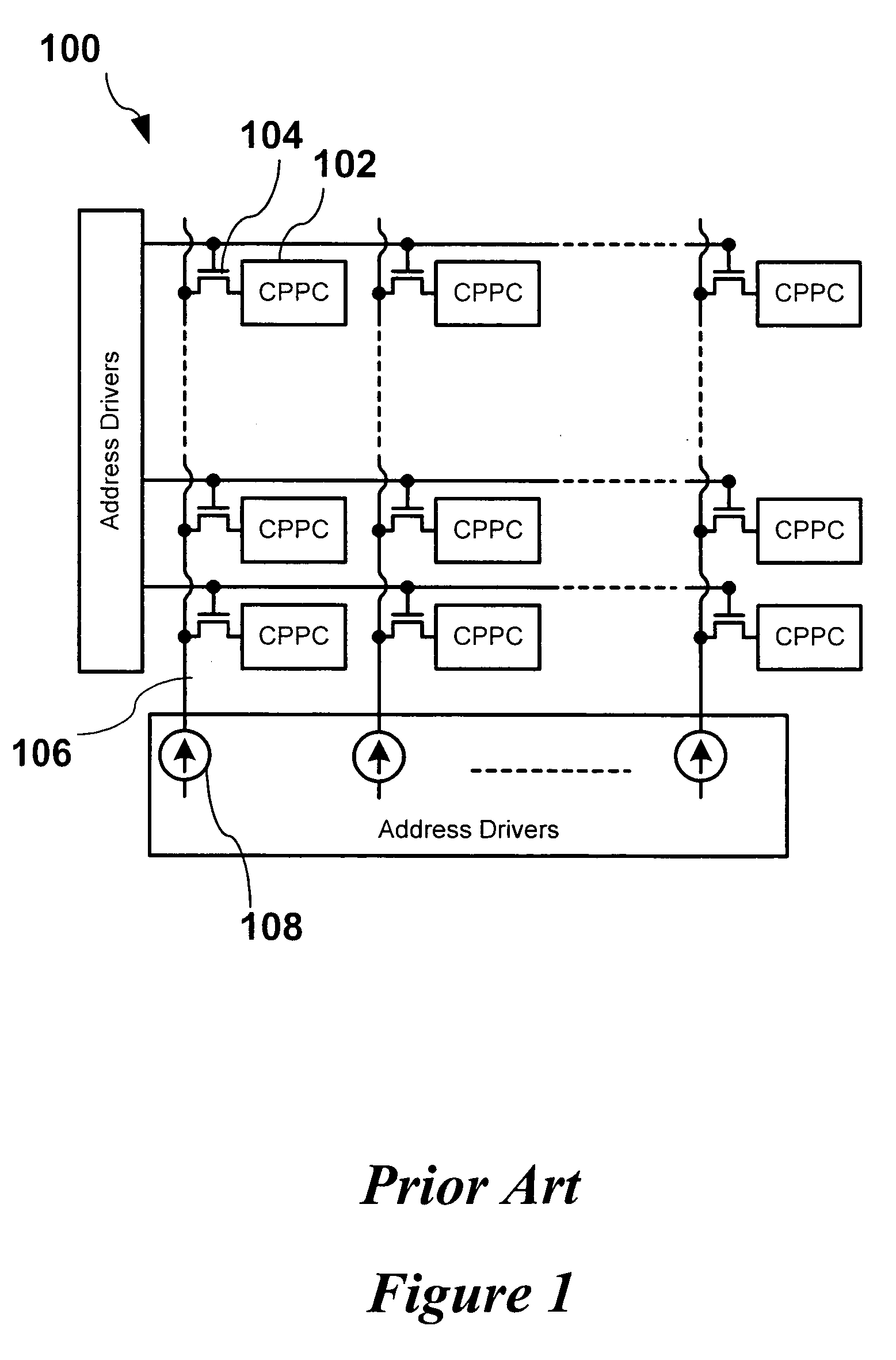
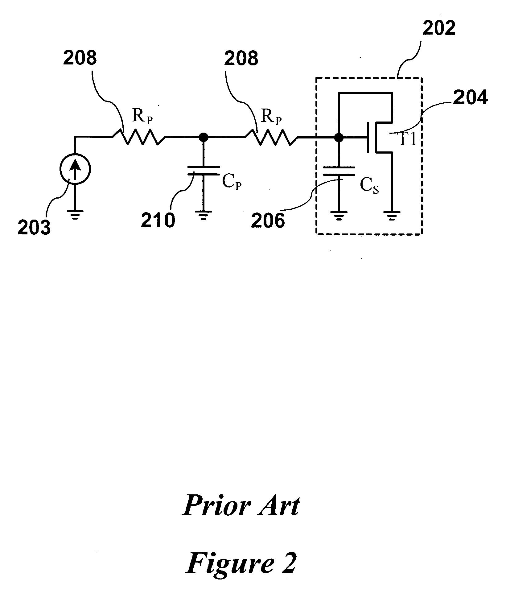
However, the parasitic capacitance contributed from the line and select transistors connected to the line results in a large settling time.
Although, the settling time can be improved partially by pre-charging, the improvement is not sufficient for medium and large area displays.
However, the timing budget of the programming cycle is less than 100 μs for large area displays.
This parasitic capacitance thus contributes to a high settling time for current programmed pixels, limiting the timing budget of the programming cycle.
This can cause considerable error due to imperfect settling.
However, the drawback of this circuit is that it has a high power consumption resulting from resistor R 304.
The other drawback of this circuit is that it suffers from mismatch.
The spatial mismatch changes the value of resistor R 304 causing non-uniformity in the display.

Method used


Image

  • Driving circuit for current programmed organic light-emitting diode displays
  • Driving circuit for current programmed organic light-emitting diode displays
  • Driving circuit for current programmed organic light-emitting diode displays

Examples


Embodiment Construction

[0034] As outlined in the discussion of FIG. 2 the settling of the time of the current can be larger than that allowed because of the parasitic capacitance. Embodiments of the invention consider the use of a feedback circuit to provide positive feedback to a current source. This feedback allows for an improvement in the settling time of the current allowing current driven displays to have the necessary response times.

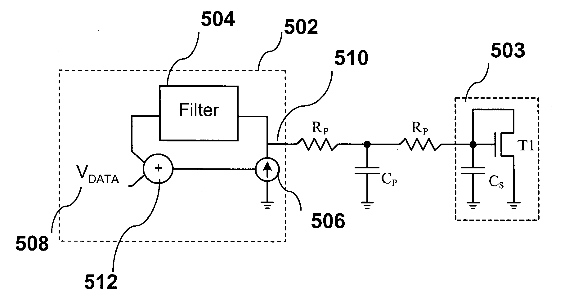
[0035] A basic feedback circuit according to one embodiment of the invention is shown in FIG. 5. A display drive circuit 502 is used to drive a light-emitting pixel 503. The drive circuit 502 includes a voltage controlled current source (VCCS) 506 and a feedback loop. Within this feedback loop is a filter 504 and a voltage adder 512. The current source 506 is controlled by VDATA 508 and the output of the filter 504, which monitors the voltage of data line 510. The current source 506, filter 504, and voltage adder 512 are part of the display driver 502 that can be imple...


PUM


Abstract

A load driving circuit for a load having a parasitic capacitance associated therewith is provided. The load being current programmed. The driving circuit has a data line having a voltage controlling the load, a feedback loop having a lowpass filter for monitoring the voltage of the data line; and a current source for providing a current to the data line; the current source being controlled by a signal line and an output from the lowpass filter.

Description

FIELD OF INVENTION [0001] The present invention relates to methods and apparatus for driving a current line with a parasitic capacitance. In particular, the present invention relates to methods and apparatus for driving organic light-emitting diode (OLED) displays that are current programmed. BACKGROUND OF THE INVENTION [0002] Maturing of Flat Panel Display (FPD) technologies has provided larger and lower cost laptop monitors, small area / low power panels for cell phones and other portable devices, HDTV and widescreen formats for home television, and high reliability daylight readable displays for “glass cockpits” for aircraft. [0003] Emerging technologies such as organic LEDs (OLED) promise to deliver higher quality emissive flat displays, allowing the removal of the backlight. When compared to LCDs, a thinner form-factor with almost perfect viewing angle and much faster response speed would be provided by OLEDs. Thus the intrinsic characteristics of OLEDs give visual and form facto...

Claims


Application Information

Patent Timeline
Patent Type & Authority Applications(United States)
IPC IPC(8): G09G3/06G09G3/32G09G3/3208H05B44/00
CPCG09G3/3241G09G3/3283G09G2310/0248G09G2320/0252G09G2320/0295G09G2330/06H05B33/08H05B45/00Y02B20/30H01L2224/037H01L2924/12044H05B44/00
Inventor NATHAN, AROKIACHALI, GHOLAMREZA REZA
Owner IGNIS INNOVATION
Learn More