Broadband planar inverted F antenna

a planar inverted antenna, broader bandwidth technology, applied in the direction of antennas, antenna details, electrical devices, etc., to achieve the effect of increasing the useable bandwidth of a pifa and increasing the volume (thickness) of the antenna

Inactive Publication Date: 2005-04-19
SIEMENS AG
View PDF16 Cites 18 Cited by
  • Summary
  • Abstract
  • Description
  • Claims
  • Application Information

AI Technical Summary

Benefits of technology

[0006]The present invention overcomes the above-identified problems as well as other shortcomings and deficiencies of existing technologies by providing an apparatus, system and method for increasing the useable bandwidth of a PIFA without having to increase the volume (thickness) thereof.

Problems solved by technology

A significant problem in designing a practical PIFA application is the trade off between obtaining a desired operating bandwidth and reducing the PIFA volume (area×thickness).

Method used


Image

  • Broadband planar inverted F antenna
  • Broadband planar inverted F antenna
  • Broadband planar inverted F antenna

Examples


Embodiment Construction

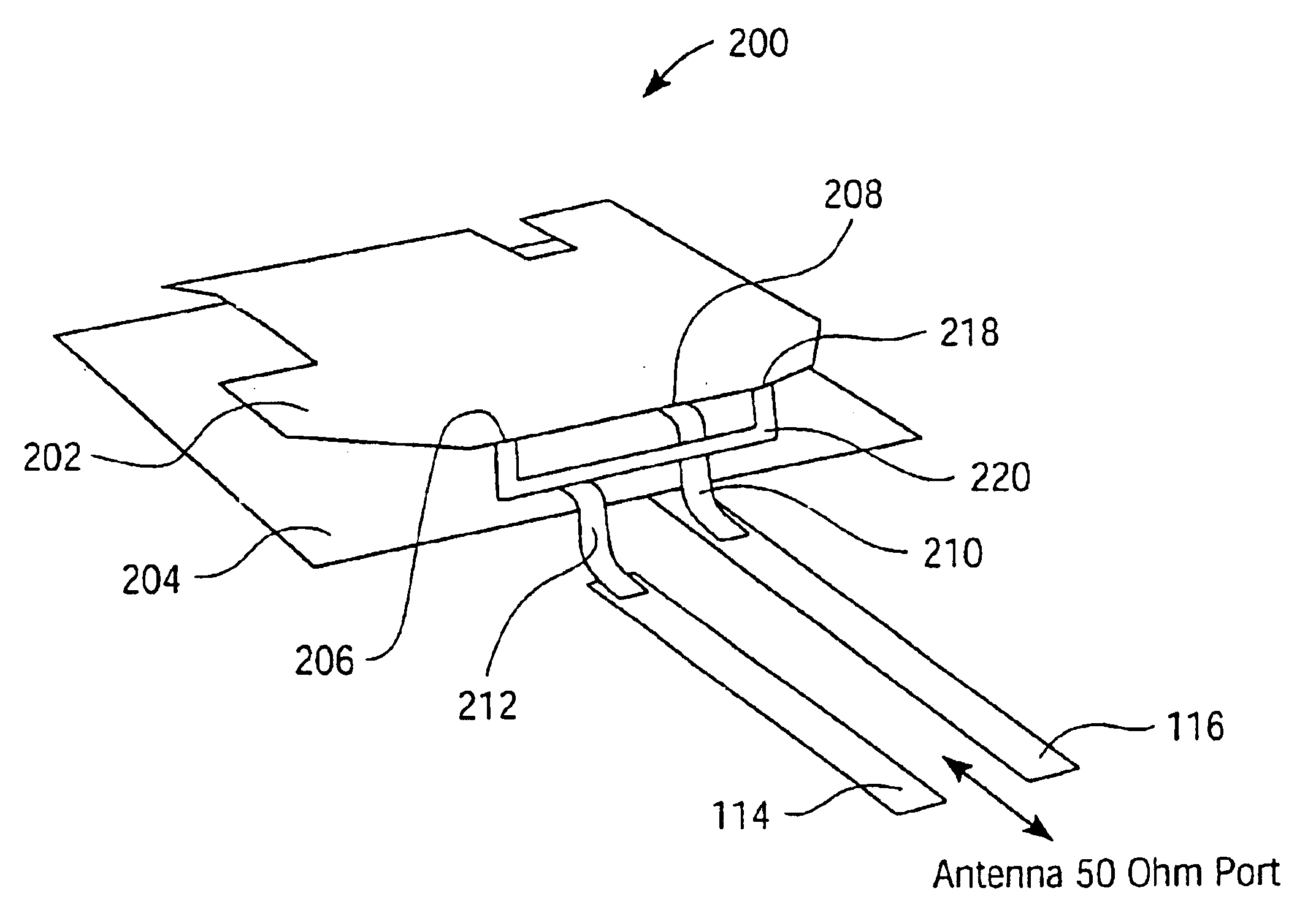
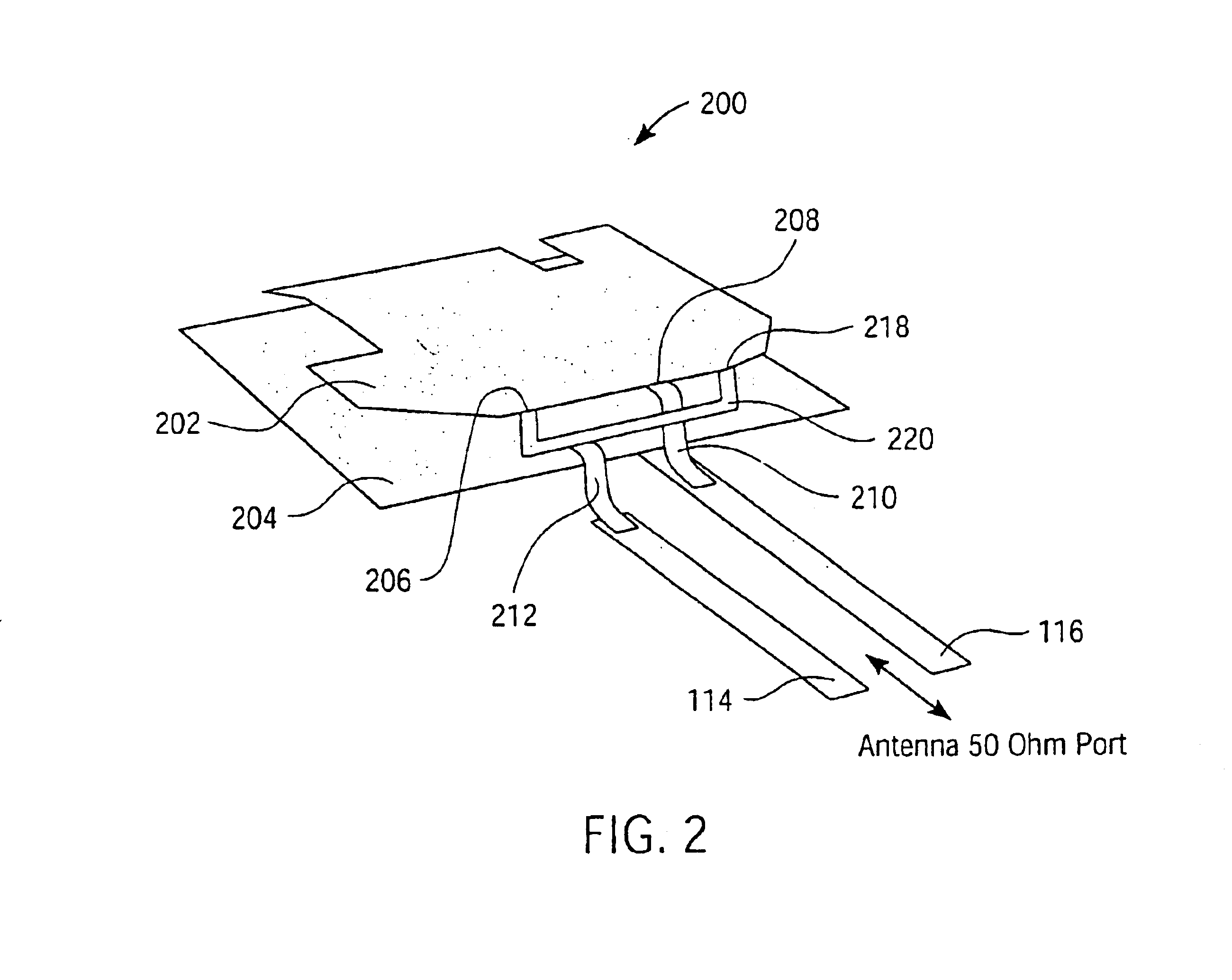
[0014]According to an exemplary embodiment of the invention, a mono-band PIFA structure includes a planar radiating element having a first area, and a ground plane having a second area that is substantially parallel to the radiating element first area. An electrically conductive first line is coupled to the radiating element at a first contact located at an edge on a side of the radiating element. The first line is also coupled to the ground plane. An electrically conductive second line is coupled to the radiating element at second and third contacts located along the same side as the first contact, but at different locations on the edge than the first contact. The first and second lines are adapted for a desired impedance, e.g., 50 ohms, at frequencies of operation of the PIFA.

[0015]In accordance to the present invention, connecting the second line to the radiating element at more than one contact location results in enhanced bandwidth for a give volume PIFA structure. The addition...


PUM


Abstract

A mono-band planar inverted F antenna (PIFA) structure comprises a planar radiating element having a first area, and a ground plane having a second area that is substantially parallel to the radiating element first area. An electrically conductive first line is coupled to the radiating element at a first contact located at an edge on a side of the radiating element. The first line is also coupled to the ground plane. An electrically conductive second line is coupled to the radiating element at second and third contacts located along the same side as the first line, but at different locations on the edge than the first contact. Useable bandwidth of the PIFA is increased by using multiple contact locations to couple the conductive second line to the radiating element. The first and second lines are adapted to couple to a desired impedance, e.g., 50 ohms, at frequencies of operation of the PIFA.

Description

BACKGROUND OF THE INVENTION[0001]The present invention relates generally to antennas and more particularly to a broader bandwidth isotropic planar inverted F antenna.[0002]Planar inverted F antennas (PIFAs) are used in wireless communications, e.g., cellular telephones, wireless personal digital assistants (PDAs), wireless local area networks (LANs)—Bluetooth, etc. The PIFA generally includes a planar radiating element having a first area, and a ground plane having a second area that is parallel to the radiating element first area. An electrically conductive first line is coupled to the radiating element at a first contact located at an edge on a side of the radiating element. The first line is also coupled to the ground plane. An electrically conductive second line is coupled to the radiating element along the same side as the first line, but at a different contact location on the edge than the first line. The first and second lines are adapted to couple to a desired impedance, e.g...

Claims


Application Information

Patent Timeline
Patent Type & Authority Patents(United States)
IPC IPC(8): H01Q5/00H01Q9/04H01Q1/24H01Q5/50
CPCH01Q1/243H01Q5/50H01Q9/0421H01Q1/38H01Q13/08
Inventor NEVERMANN, PETER
Owner SIEMENS AG
Why Eureka
Try Eureka