Digital demodulating device in a digital TV receiver

a demodulating device and digital tv technology, applied in the field of digital tv, can solve the problems of degrading the performance of the dtv receiver, detecting wrong timing error information, etc., and achieve the effect of maximizing the signal-to-noise ratio and reducing the error

Inactive Publication Date: 2005-04-19
LG ELECTRONICS INC
View PDF6 Cites 19 Cited by
  • Summary
  • Abstract
  • Description
  • Claims
  • Application Information

AI Technical Summary

Benefits of technology

[0040]In other aspect of the present invention, a digital demodulating method in a digital TV receiver includes the steps of: a) digitizing pass band signals of a particular channel transmitted in a VSB modulation mode; b) multiplying the pass band digital signals by a complex sinusoidal wave with a recovered carrier wave to convert the pass band digital signals to base band digital signals; c) detecting phase error of the carrier wave from pilot signals included in the base band digital signals, generating a complex sinusoidal wave relative to the phase error, and feeding back the complex sinusoidal wave to the step b); d) interpolating a timing error of current symbols to reduce an error between base band digital signals output from the step b); e) filtering an output signal of the step d) to maximize a signal-to-noise ratio (SNR) at a symbol position; f) obtaining a timing error of the current symbols from an output signal of the step e); and g) compensating channel distortion included in the output signal of the step e).

Problems solved by technology

If the timing error is detected using such a signal, wrong timing error information may be detected.
If the carrier wave is not recovered, the received data is not recovered normally, thereby degrading performance of the DTV receiver.

Method used


Image

  • Digital demodulating device in a digital TV receiver
  • Digital demodulating device in a digital TV receiver
  • Digital demodulating device in a digital TV receiver

Examples


Embodiment Construction

[0045]Reference will now be made in detail to the preferred embodiments of the present invention, examples of which are illustrated in the accompanying drawings. Wherever possible, the same reference numbers will be used throughout the drawings to refer to the same or like parts.

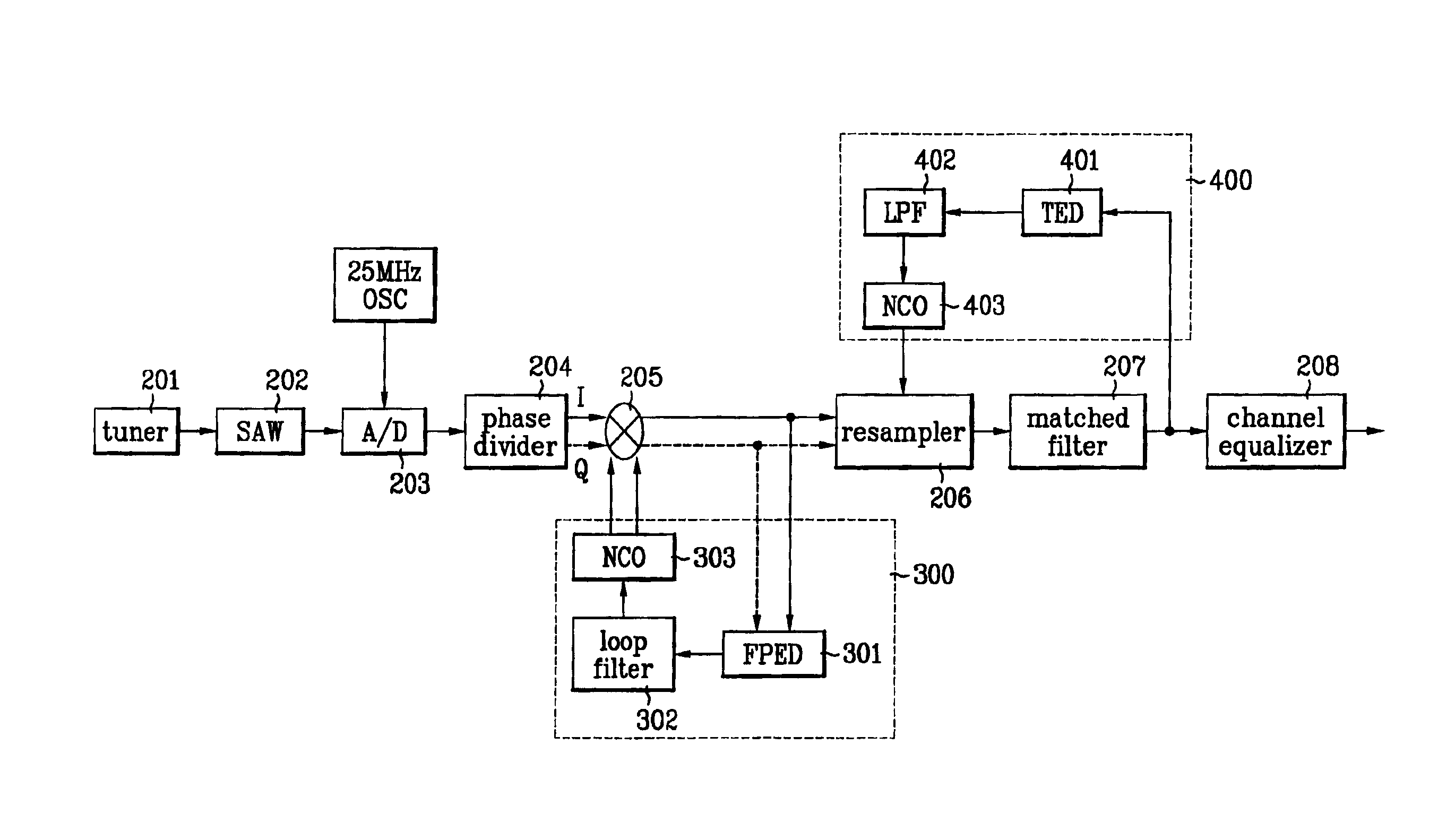
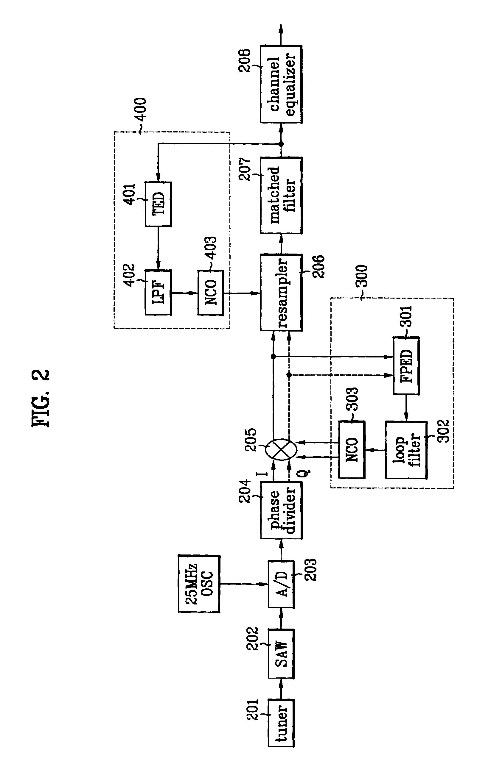
[0046]FIG. 2 is a block diagram of a DTV receiver according to the present invention. Referring to FIG. 2, the DTV receiver includes a tuner 201, a SAW filter 202, an A / D converter 203, a phase divider 204, a multiplier 205, a resampler 206, a matched filter 207, and a channel equalizer 208. Also, a carrier wave recovery portion 300 is connected with an output terminal of the multiplier 205, and a timing recovery portion 400 is connected with an output terminal of the matched filter 207.

[0047]In the present invention, for the convenience of description, the A / D converter 203, the phase divider 204, the multiplier 205, the resampler 206, the matched filter 207, the channel equalizer 208, the carrier wave reco...


PUM


Abstract

A VSB demodulating device and method in a DTV receiver is disclosed, in which a VSB signal is received for independent carrier wave recovery and symbol clock recovery. An A/D converter samples the output of a SAW filter with a fixed frequency and converts the resultant value to a digital signal. A carrier wave recovery portion recovers a carrier wave from a base band pilot signal output from a multiplier, and a timing recovery portion recovers a symbol clock used for a transmitter using the output of a matched filter disposed in a base band. In this case, the carrier wave recovery portion and the timing recovery portion are independently operated without affecting each other. Thus, the carrier wave recovery portion is operated stably even in case where a fatal ghost exists in a band used for timing recovery. Furthermore, since a closed loop control can be implemented independently for carrier wave recovery and timing recovery, stability of the system is improved, thereby improving performance of the DTV receiver.

Description

[0001]This application claims the benefit of the Korean Application No. P2001-05920 filed on Feb. 7, 2001.BACKGROUND OF THE INVENTION[0002]1. Field of the Invention[0003]The present invention relates to a digital TV(DTV), and more particularly, to a vestigial sideband (VSB) demodulating device and method in a DTV receiver, in which a VSB signal is received for independent carrier wave recovery and symbol clock recovery.[0004]2. Discussion of the Related Art[0005]Generally, a VSB mode of Grand Alliance employed as the standard of a digital TV (for example, HDTV) transmission mode in the United States of America and Korea modulates one of two side bands generated up and down based on a carrier wave when amplitude of a signal is modulated while attenuates the other. That is to say, the VSB mode transmits one side band spectrum of a base band to a pass band, so that a band region can effectively be used.[0006]In case of VSB modulation, DC spectrum of a base band is changed to a tone spe...

Claims


Application Information

Patent Timeline
Patent Type & Authority Patents(United States)
IPC IPC(8): H04L27/06H04N5/455H04L27/00H04N5/44H04N7/015
CPCH04L27/066H04N5/455H04L2027/0028H04N5/4401H04L2027/0055H04N21/426H04N21/4382H04N7/015
Inventor HONG, SUNG RYONGKIM, JOON TAE
Owner LG ELECTRONICS INC
Why Eureka
Try Eureka