Leg and bracket assembly for a bed foundation

a technology for a bed and a bracket, which is applied in the direction of beds, beds, sofas, etc., can solve the problems of not having the box springs cannot be assembled for shipping, and the consumer would likely not have the skill to properly construct the box spring, etc., to achieve the effect of quick and easy assembly

Inactive Publication Date: 2005-04-26
SLEEP NUMBER CORP
View PDF19 Cites 142 Cited by
  • Summary
  • Abstract
  • Description
  • Claims
  • Application Information

AI Technical Summary

Benefits of technology

[0016]The present invention includes a bed foundation capable of supporting a variety of mattresses. Preferably, the bed foundation is constructed entirely of blow-molded plastic components. These components interlock without the use of tools and can be quickly and easily assembled by a customer. When disassembled, the components compactly ship within a container having a length less than 60 inches and a girth less than 84 inches. When assembled, the bed foundation is inherently sturdy, attractive, and impressive.

Problems solved by technology

Because these conventional bed foundations are assembled at the factory and covered with attractive ticking, they cannot be disassembled for shipping.
If the manufacturer were to ship the parts of the box spring along with the cover and leave assembly up to the consumer, the consumer would likely not have the skill to properly construct the box spring.
These fully assembled box springs not only incur shipping penalties, they are difficult to handle, both during delivery to the consumer and by the consumer once in the consumer's home.
For example, it is not uncommon, in the case of larger sized beds such as queen beds that a box spring is unable to fit up a stairwell or around certain corners.
Thus, the bulky size of the box spring limits the number of rooms in which a homeowner can place a larger sized bed.
While these bed foundations provide a solution to the problem a conventional bed foundation poses pertaining to shipping a large, fully assembled box spring, these designs do require a significant amount of assembly by the consumer.
Bed foundations, or other products for that matter, requiring assembly, can often leave a bad impression with the customer if the assembly asked of the customer is excessive, complicated or poorly described in an instruction manual.
It is not unusual for there to be screws missing, tools missing, holes drilled in the wrong location, and missing angle irons.
These discrepancies can often create significant discontent with the customer and may even result in the customer returning the entire package and purchasing a competitor's product.
An additional problem presented by the traditional box spring is that it requires a steel rail frame assembly for supporting the box spring above the ground.
These steel bed frames encounter many of the same shipping problems and expenses mentioned above.
However, these angle iron pieces are unattractive and tend to damage the ticking of the box spring.
Particularly unattractive are the wheeled leg members typically found on these frames.
Besides being unattractive, the wheels make securing the bed in a desired location difficult and the angle iron legs can cause significant pain when kicked unintentionally.
These legs are problematic because conventional box springs are typically constructed of relatively thin pine members and do not exhibit the structural integrity required to be supported by only four, or even six, attachment points.

Method used


Image

  • Leg and bracket assembly for a bed foundation
  • Leg and bracket assembly for a bed foundation
  • Leg and bracket assembly for a bed foundation

Examples


Embodiment Construction

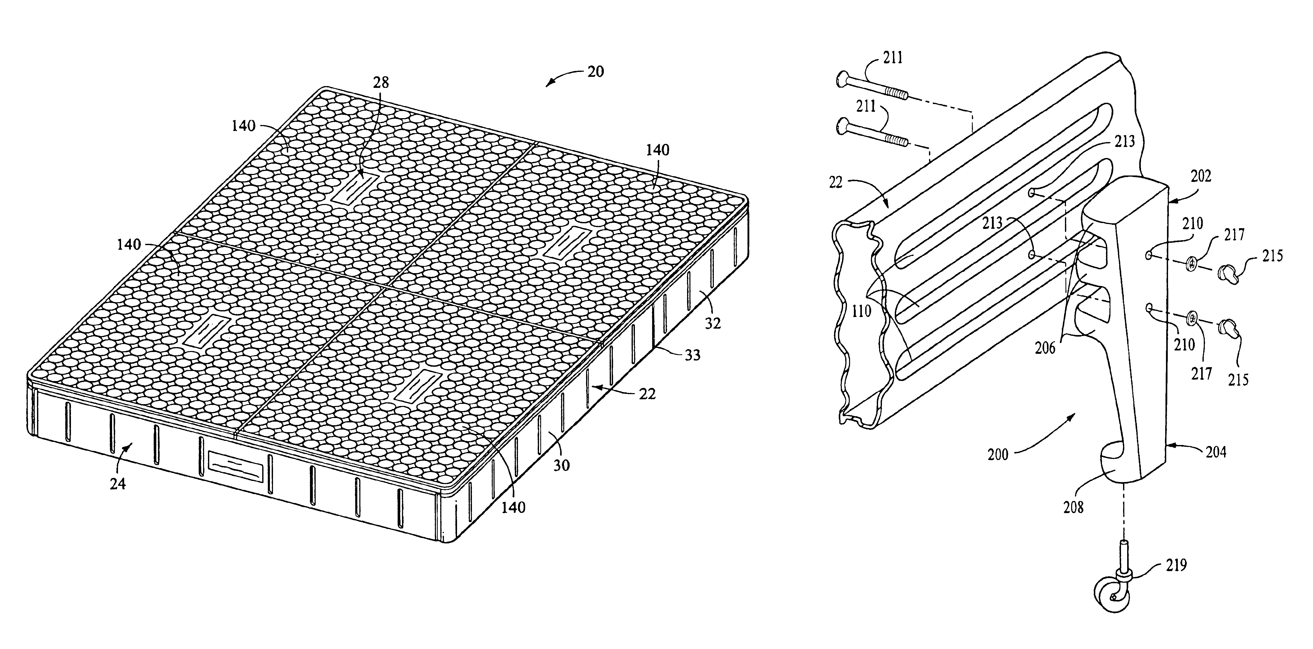
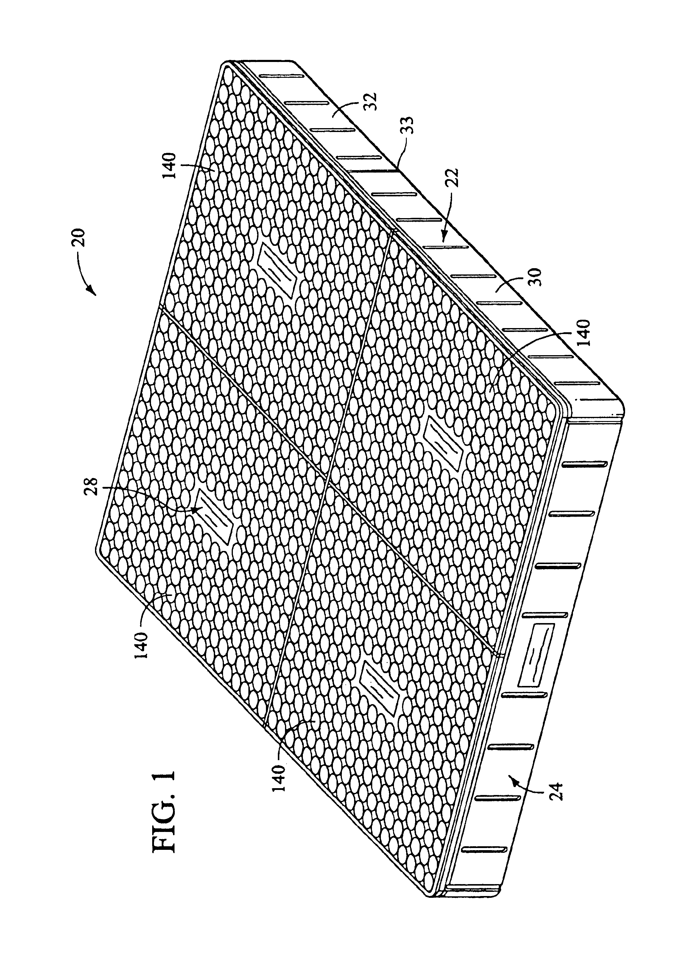
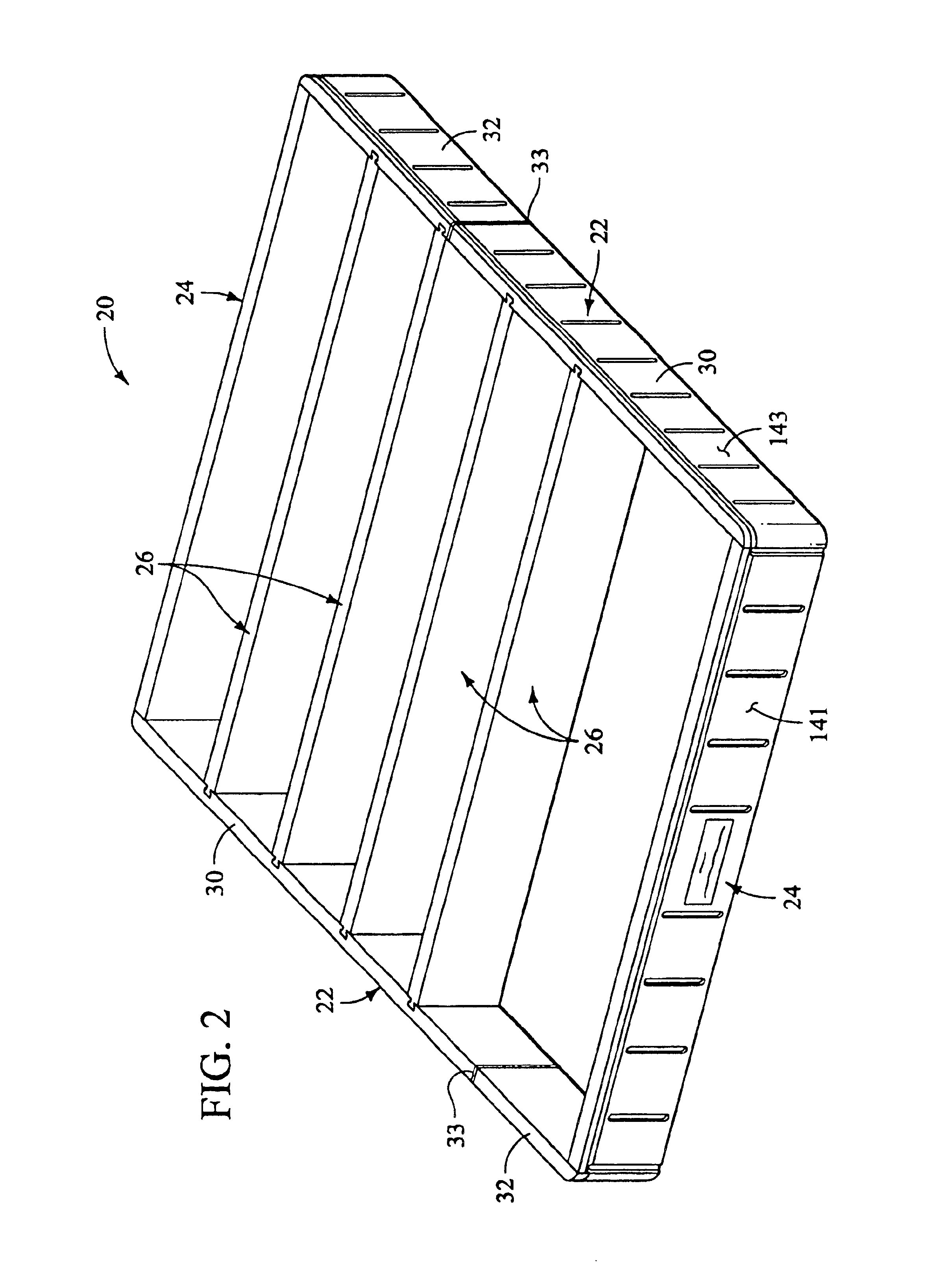
[0042]Referring now to the drawings in first to FIGS. 1 and 2, a bed foundation 20 is provided which includes a pair of side rails 22, a pair of end rails 24, at least one intermediate rail 26, and a top panel 28. The side rails 22, the end rails 24, the intermediate rails 26, and the top panel 28 are all preferably blow-molded from plastic.

[0043]The components of the bed foundation 20 permit reversible assembly so that the bed foundation 20 may be shipped to the customer in packages that do not incur sized-based penalties when shipping. The bed foundation 20 is constructed and arranged to permit the customer to assemble and disassemble the bed foundation 20 so it may be later stored in a relatively small space when a customer is not using the foundation 20.

[0044]The components of the foundation 20 include interlocking joints that enable the foundation 20 to be assembled without the use of tools. These interlocking joints are integrally molded with the components so that no other pa...


PUM


Abstract

A bed foundation is provided which is constructed of blow-molded plastic and may be assembled without using tools. The components of the bed foundation all have lengths of less than 60 inches and may be packaged together in a container having a length less than 60 inches and a girth less than 84 inches, so as to avoid shipping penalties. The components are constructed and arranged to allow disassembly and storage when the foundation is not in use. One embodiment provides a bed foundation that, when assembled, has a top panel which overhangs the side rails to permit an oversized mattress to be placed thereon. Additionally, bed legs are provided that are configured to mate with contours in the foundation.

Description

CROSS REFERENCE TO RELATED APPLICATIONS[0001]This invention is a continuation-in-part of U.S. patent application Ser. No. 09 / 900,685 filed Jul. 6, 2001, now abandoned which is related to Provisional Application No. 60 / 216,908, filed Jul. 7, 2000, and are incorporated herein by reference in their entirety.BACKGROUND OF THE INVENTION[0002]Despite the remarkable advances made in manufacturing processes over the last several decades, conventional bed foundations have, for the most part, dated designs and are assembled using old techniques. These foundations, commonly known as box springs, consist of a plurality of wood members combined with rigid metal springs constructed and arranged to form a rectangular box which provides a relatively rigid platform on which to place a mattress. The bottom of the box spring or bed foundation, having rigid members, is capable of being supported by a bed frame having two side rails and one or two cross members.[0003]Because these conventional bed found...

Claims


Application Information

Patent Timeline
Patent Type & Authority Patents(United States)
IPC IPC(8): A47C19/00
CPCA47C19/005
Inventor GABOURY, JAMES D.GIFFT, JAMES E.KOUGHAN, DANIEL J.BETH, BRIAN C.SMITH, DONALD J.ANDREINI, MICHAEL A.CARLSON, ALAN L.WARD, KEVIN J.
Owner SLEEP NUMBER CORP
Why Eureka
Try Eureka