Connecting configuration for a diaphragm in a diaphragm pump

a diaphragm pump and diaphragm technology, which is applied in the direction of positive displacement liquid engines, flexible wall reciprocating engines, positive displacement engines, etc., can solve the problems of pump performance, complete operation failure of the pump, and potential leakage path between the air chamber and the fluid chamber, etc., and achieve the effect of manufacturing costs

Inactive Publication Date: 2005-04-26
INGERSOLL RAND IND U S INC
View PDF79 Cites 27 Cited by
  • Summary
  • Abstract
  • Description
  • Claims
  • Application Information

AI Technical Summary

Benefits of technology

[0004]Another conventional practice for coupling the connecting rod to the diaphragm involves overmolding an insert to create the diaphragm. Generally, the insert includes a threaded stud protruding from the insert to engage threads formed in a recess of the connecting rod. Alternatively, the insert includes a threaded recess to engage a threaded end of the connecting rod. This practice effectively eliminates the possibility of a leak path between the air and fluid chambers of the pump through the diaphragm. However, additional manufacturing costs are incurred due to the sensitive process (i.e., heating, pouring, and curing of the diaphragm material, etc.) of overmolding the insert to create the diaphragm. If the process is not carefully controlled, delamination of the diaphragm often results, leading to operational failure of the pump.
[0005]The present invention provides a diaphragm pump including at least one diaphragm having an inner diaphragm surface, an outer diaphragm surface, and a projecting rim projecting from the inner diaphragm surface. The projecting rim includes an inner circumferential surface and an outer circumferential surface. A hub is positioned to lie within the inner circumferential surface of the projecting rim and a ring is positioned around the outer circumferential surface of the projecting rim. The hub and ring secure the projecting rim there between, and a reciprocating rod is coupled to at least one of the hub and the ring.

Problems solved by technology

This practice results in creating a potential leak path between the air chamber and fluid chamber, which ideally is fluidly separated by the diaphragm.
Also, loosening of the fasteners may affect the pump's performance, and may eventually lead to complete operational failure of the pump.
However, additional manufacturing costs are incurred due to the sensitive process (i.e., heating, pouring, and curing of the diaphragm material, etc.) of overmolding the insert to create the diaphragm.
If the process is not carefully controlled, delamination of the diaphragm often results, leading to operational failure of the pump.

Method used


Image

  • Connecting configuration for a diaphragm in a diaphragm pump
  • Connecting configuration for a diaphragm in a diaphragm pump
  • Connecting configuration for a diaphragm in a diaphragm pump

Examples


Embodiment Construction

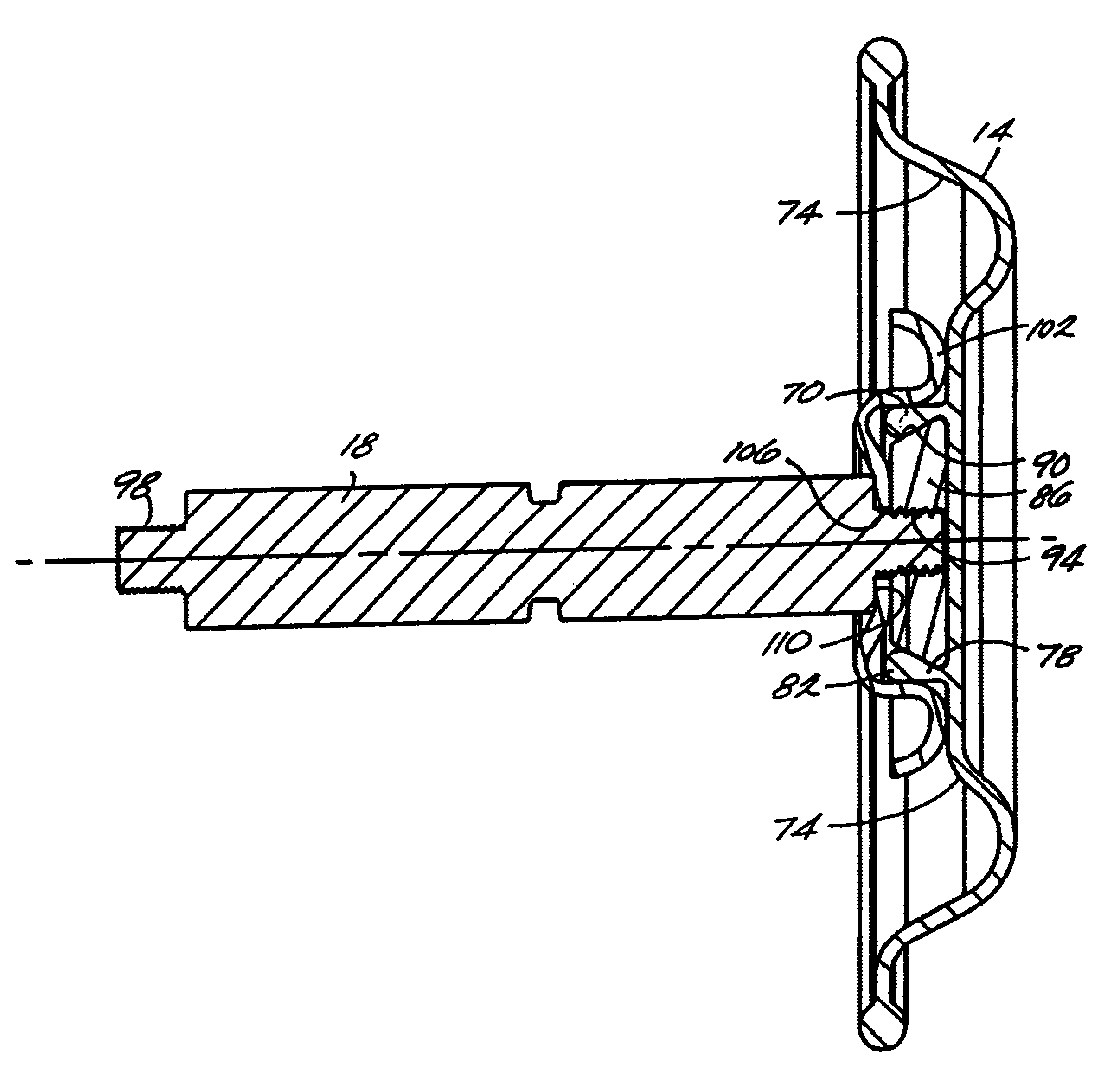
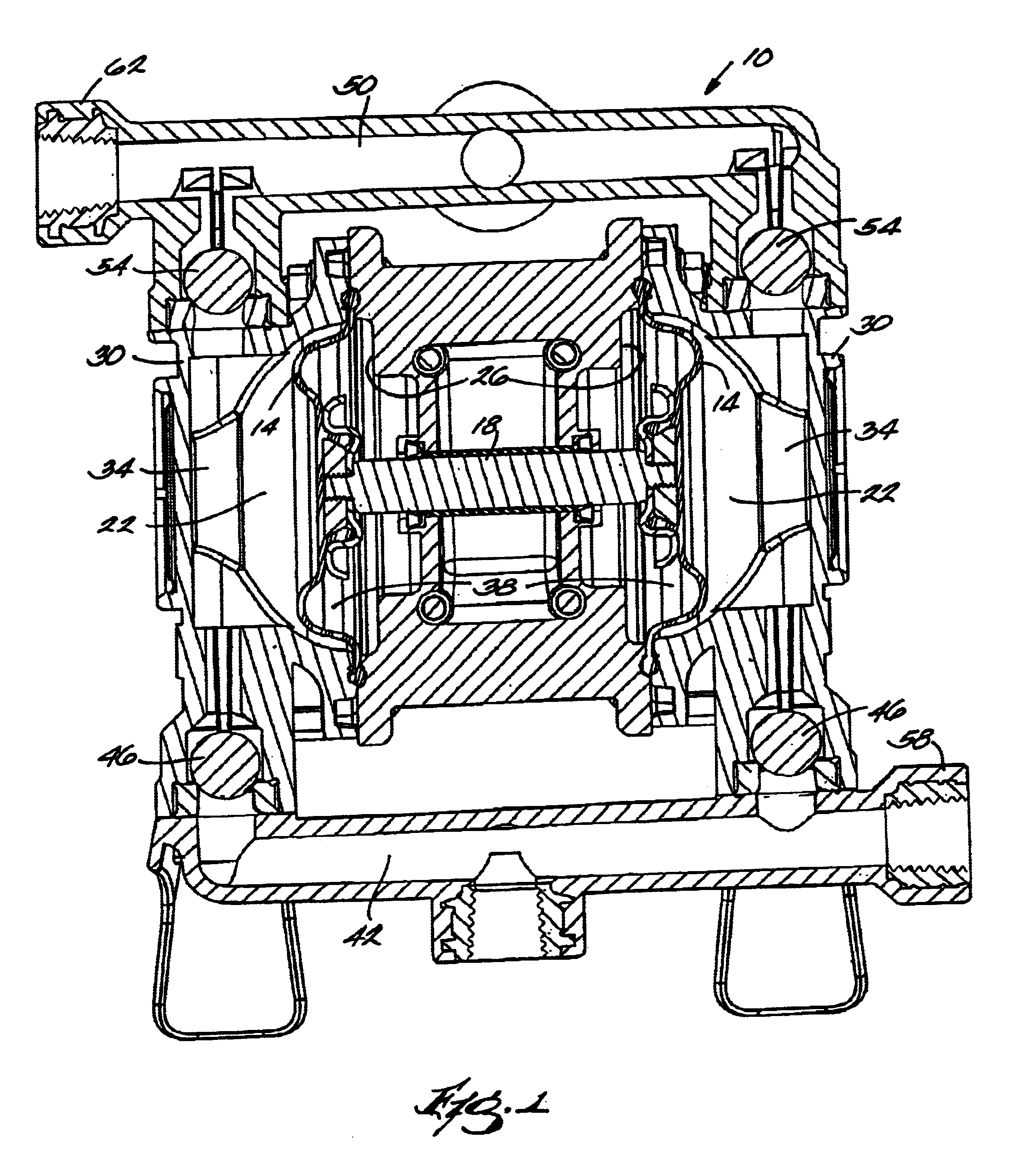
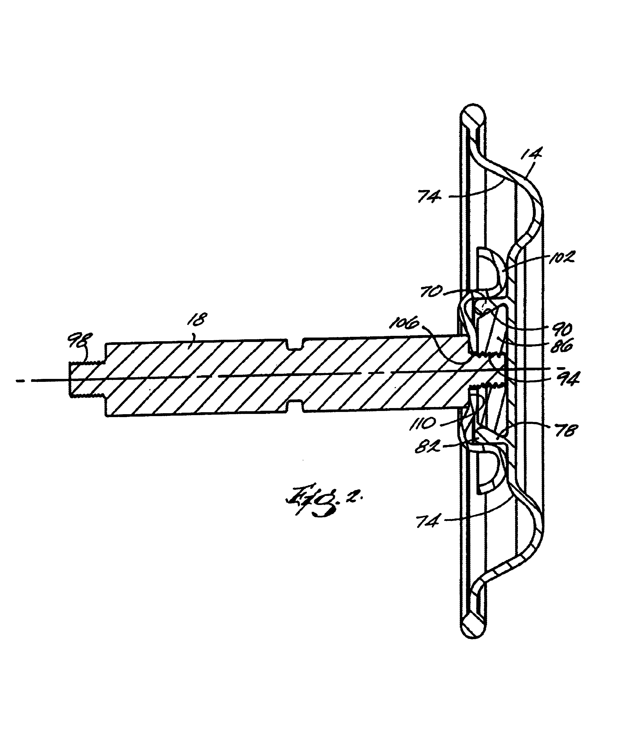
[0015]With reference to FIG. 1, a double diaphragm pump 10 is shown including a connecting configuration according to the present invention between a diaphragm 14 and a connecting rod 18. However, as will be readily apparent to those of ordinary skill in the art, the connecting configuration is not limited for use in double diaphragm pumps 10 only. The connecting configuration may also be used, for example, in a single diaphragm pump, as well as other types of diaphragm pumps.

[0016]The double diaphragm pump 10 includes two pumping cavities 22 formed between an air cap 26 and a fluid cap 30. Each cavity 22 includes a fluid chamber 34 and an air chamber 38, the chambers 34, 38 being separated by the diaphragm 14 spanning the width of the cavity 22. The diaphragms 14 are interconnected by the connecting rod 18, such that forced movement of one diaphragm 14 imparts opposite movement to the other diaphragm 14. Each fluid chamber 34 is selectively fluidly connected to an inlet manifold 42...


PUM


Abstract

A diaphragm pump including at least one diaphragm having an inner diaphragm surface, an outer diaphragm surface, and a projecting rim, the rim projecting from the inner diaphragm surface and having an inner circumferential surface and an outer circumferential surface, a hub positioned to lie within the inner circumferential surface of the projecting rim, a ring positioned around the outer circumferential surface of the projecting rim, where the hub and ring secure the projecting rim there between, and a reciprocating rod coupled to at least one of the hub and the ring.

Description

BACKGROUND OF THE INVENTION[0001]This invention relates generally to diaphragm pumps, and more particularly to air operated diaphragms of diaphragm pumps.[0002]Diaphragm pumps are widely known in the art and are used in pumping a wide variety of fluids. Generally, the most critical driving element of the diaphragm pump is the diaphragm. The diaphragm is typically a circular membrane made of a flexible material, such as rubber or a thermoplastic elastomer. In the case of an air-operated diaphragm pump, the diaphragm separates an air chamber from a fluid chamber. Reciprocal movement of the diaphragm creates pressure variations within the fluid chamber that causes the fluid to pump through the fluid chamber. One type of diaphragm pump, a double-diaphragm pump, is also widely known in the art and provides a nearly constant flow of fluid from the pump by utilizing two reciprocating, interconnected diaphragms.SUMMARY OF THE INVENTION[0003]To impart reciprocal movement to the diaphragm, a ...

Claims


Application Information

Patent Timeline
Patent Type & Authority Patents(United States)
IPC IPC(8): F04B43/00
CPCF04B43/0054
Inventor HEADLEY, THOMAS R.TOWNE, LLOYD I.
Owner INGERSOLL RAND IND U S INC
Why Eureka
Try Eureka