
Vehicle control system capable of controlling electric-power generation state of vehicle alternator

Active Publication Date: 2009-07-30
DENSO CORP
View PDF9 Cites 27 Cited by
  • Summary
  • Abstract
  • Description
  • Claims
  • Application Information

AI Technical Summary

Benefits of technology

[0009]It is an object of the present invention to provide a vehicle control system capable of informing the occurrence of abnormal state of detection means for a battery, for example, a current sensor a voltage sensor, and a temperature sensor with certainly without increasing an area of packaging an instrument panel and its manufacturing cost.
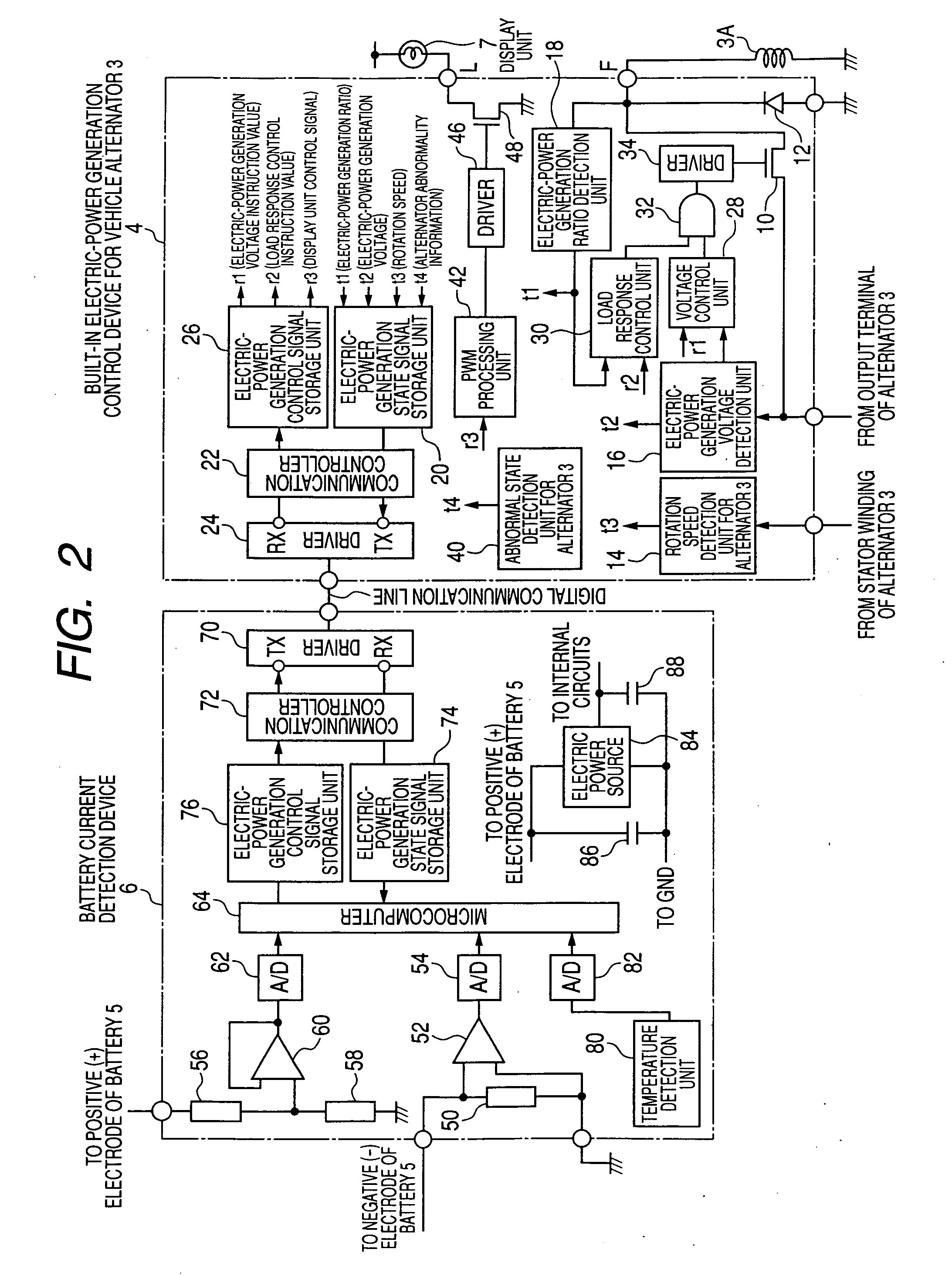
[0012]It is not necessary to equip the vehicle with any special display unit or any additional display unit to inform the abnormality information of each detection means because the vehicle control system informs the occurrence of abnormal state of each detection means through the display unit which is already mounted to the vehicle alternator. This structure can avoid increasing any area of packaging the instrument panel and the manufacturing cost of the vehicle control system. Still further, because the vehicle control system according to the present invention transfers the abnormality information between the battery current detection device and the vehicle alternator through the digital communication line, it is possible to reduce the influence of noise caused in the data transmission. Still further, because the vehicle control system can transfer the abnormality information to the vehicle alternator in order to inform the occurrence of abnormal state of each detection means without using any electric control unit (ECU), this can reduce the processing load of the ECU.

Problems solved by technology

This further increases the total manufacturing cost thereof.

Method used


Image

  • Vehicle control system capable of controlling electric-power generation state of vehicle alternator
  • Vehicle control system capable of controlling electric-power generation state of vehicle alternator
  • Vehicle control system capable of controlling electric-power generation state of vehicle alternator

Examples


embodiment

[0024]A description will be given of the vehicle control system according to an embodiment of the present invention with reference to FIG. 1 to FIG. 9.

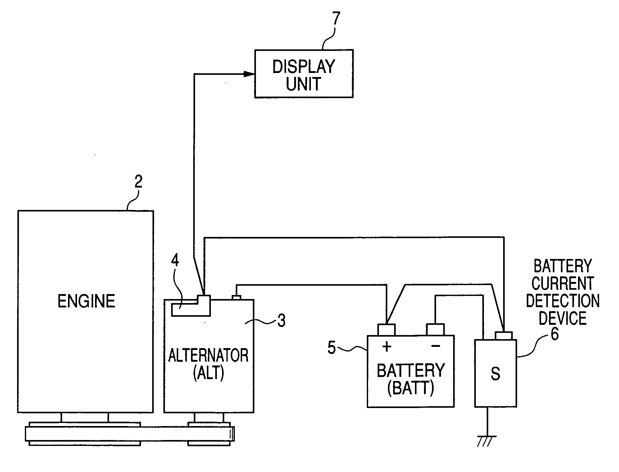
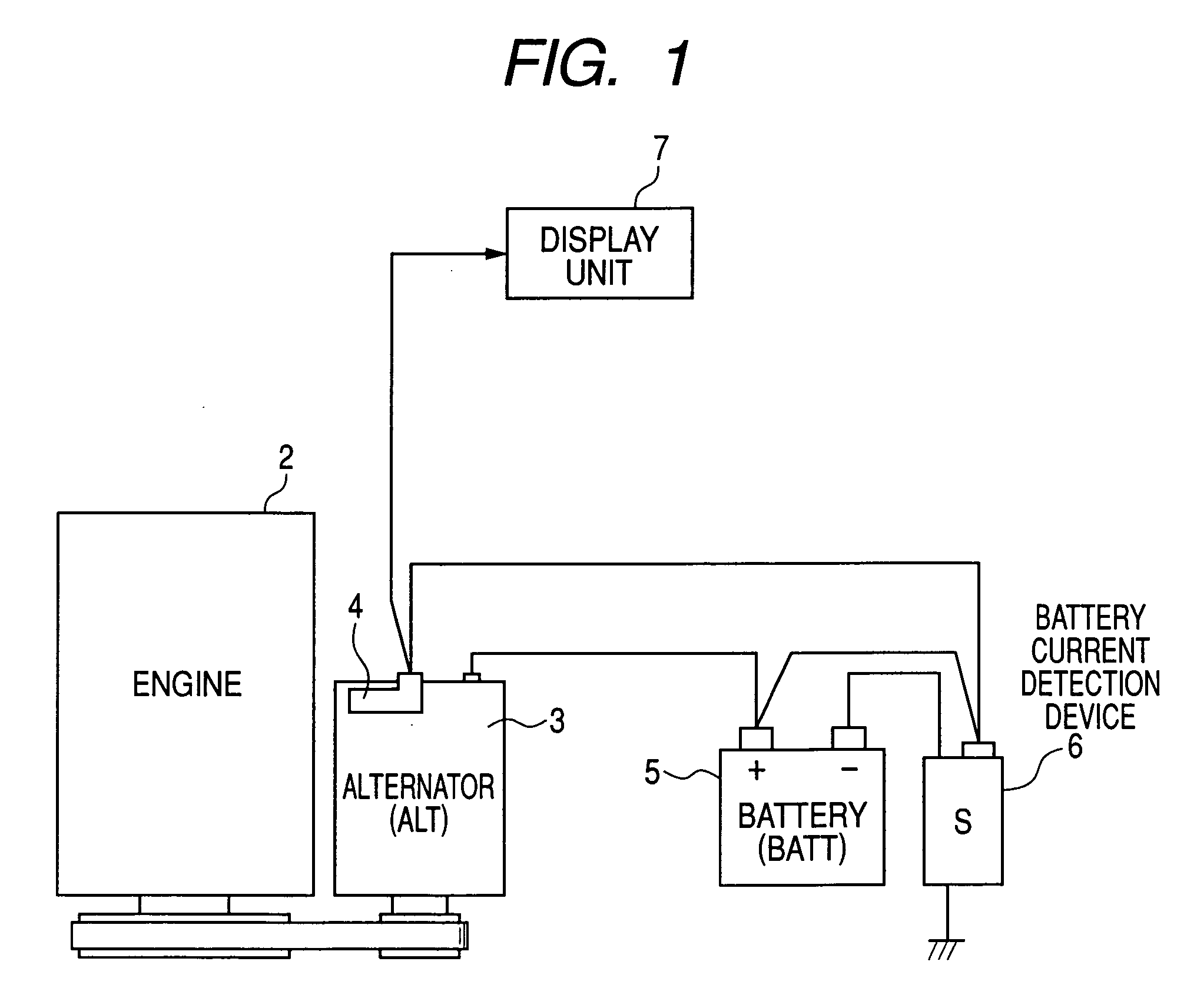
[0025]FIG. 1 is a diagram showing a schematic entire structure of the vehicle control system according to an embodiment of the present invention. As shown in FIG. 1, the vehicle control system is comprised of an internal combustion engine 2 (or the “engine 2” for short), a vehicle alternator (ALT) 3, a car battery (BATT) 5 (which will be referred to as the “battery 5” for short), a battery current detection device (S) 6, and a display unit 7. The vehicle alternator 3 has a built-in electric power generation control device 4 (hereinafter, which will be referred to as the “electric power generation control device 4” for short, and explained later in detail) with the display unit 7. The display unit 7 is electrically connected to a lamp (L) terminal of the electric power generation control device 4.

[0026]The vehicle alternator 3 rotates ...


PUM


Abstract

A vehicle control system has a battery, a vehicle alternator for charging the battery, a vehicle-alternator control device capable of controlling the vehicle alternator, and a battery current detection device. The battery current detection device has a battery current detecting means capable of detecting a charging / discharging current of the battery, a battery voltage detection means capable of detecting a voltage of the battery, a battery temperature detection means capable of detecting a temperature of the battery, a microcomputer, and a communication controller. The communication controller performs digital data communication to transfer digital control signals between the vehicle alternator and the battery current detection device. The vehicle alternator has a display unit to display the occurrence of abnormal information of those detection means transferred from the battery current detection device, the occurrence of a battery failure, and a disconnecting of a charging wire of the battery by using different display patterns.

Description

CROSS-REFERENCE TO RELATED APPLICATION[0001]This application is related to and claims priority from Japanese Patent Application No. 2008-16086 filed on Jan. 28, 2008, the contents of which are hereby incorporated by reference.BACKGROUND OF THE INVENTION[0002]1. Field of the Invention[0003]The present invention relates to vehicle control systems capable of controlling electric-power generation state of a vehicle alternator based on a battery condition mounted to vehicles such as passenger vehicles and trucks.[0004]2. Description of the Related Art[0005]There is a well-known sensor failure detection device equipped with a data processing unit and a special display unit mounted to a vehicle. The data processing unit detects the occurrence of a current sensor failure and a voltage sensor failure. The current sensor detects a charging current and a discharging current of a battery. On the other hand, the voltage sensor detects the output voltage of the battery. The display unit displays ...

Claims


Application Information

Patent Timeline
IPC IPC(8): H02J7/24
CPCB60R16/0232H01M10/48H02J7/1461H01M10/488H02J7/1453H01M10/486H02J7/007194Y02E60/10H02J7/0029H02J7/0048H02J7/005H02J7/14H02J7/007192
Inventor ABE, KUNIHIRO
Owner DENSO CORP
Learn More