Detection circuit including a noise reducing module

Active Publication Date: 2015-08-20
LYNRED
View PDF1 Cites 1 Cited by
  • Summary
  • Abstract
  • Description
  • Claims
  • Application Information

AI Technical Summary

Benefits of technology

[0009]The object of the invention is a detection circuit easy to implement

Problems solved by technology

As a consequence, circuits have been provided with additional correction blocks which present numerous problems of integra

Method used


Image

  • Detection circuit including a noise reducing module
  • Detection circuit including a noise reducing module
  • Detection circuit including a noise reducing module

Examples


Example

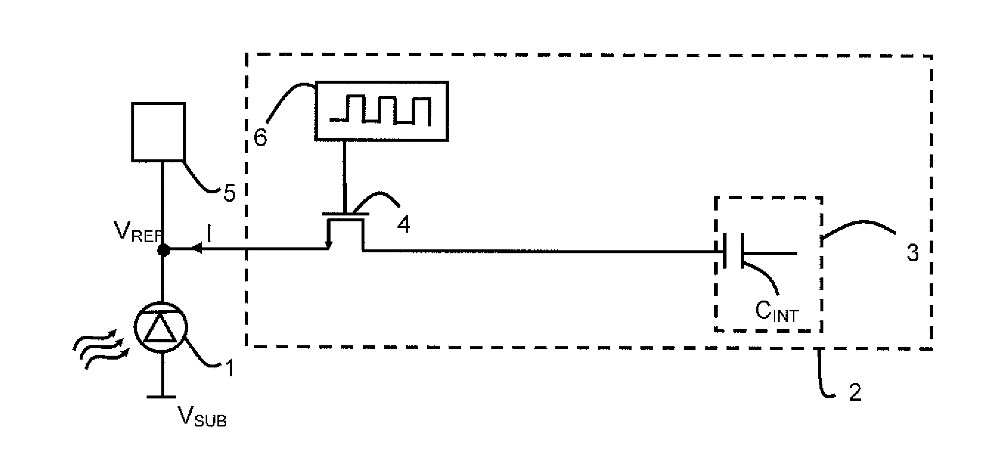
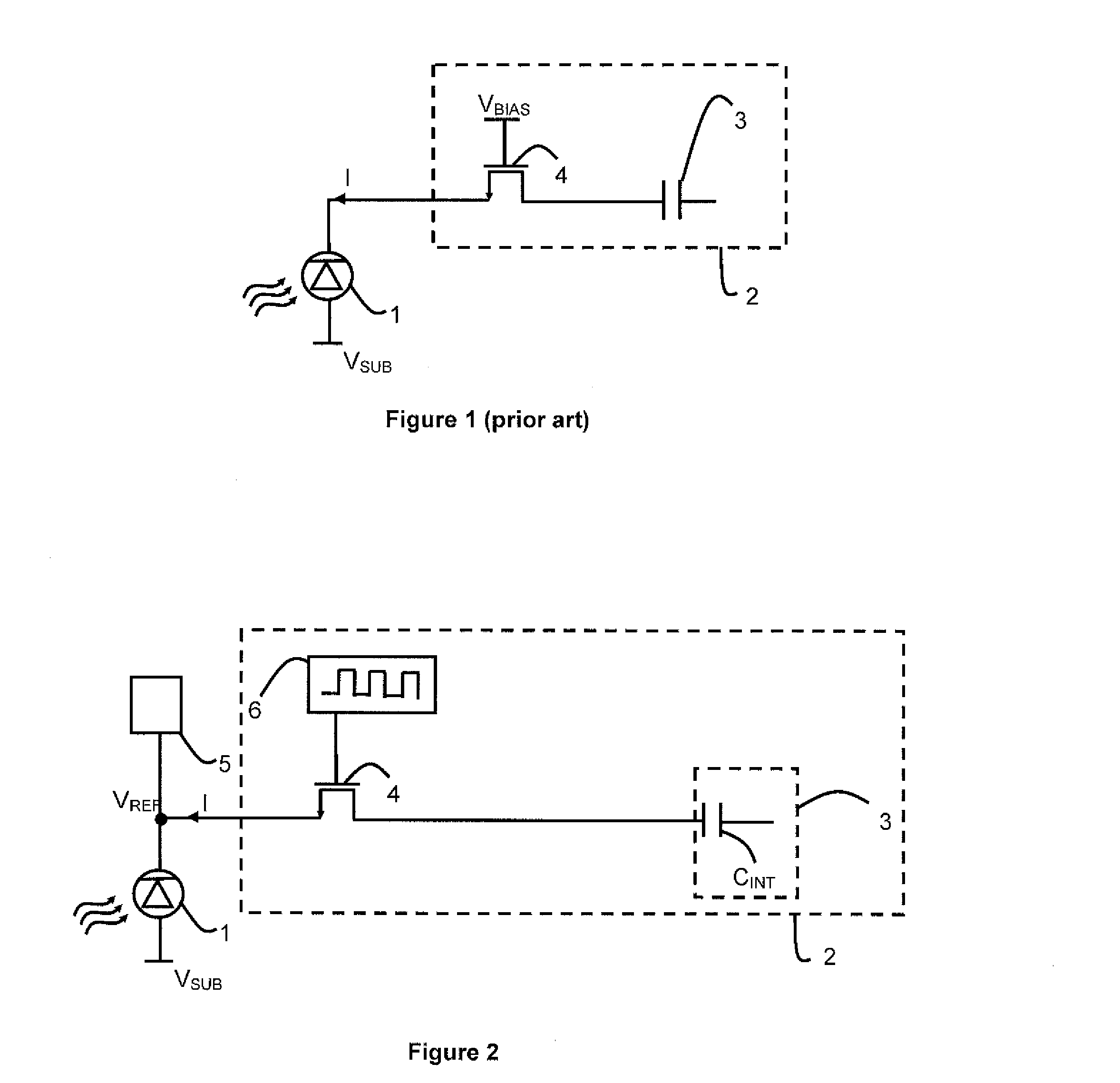
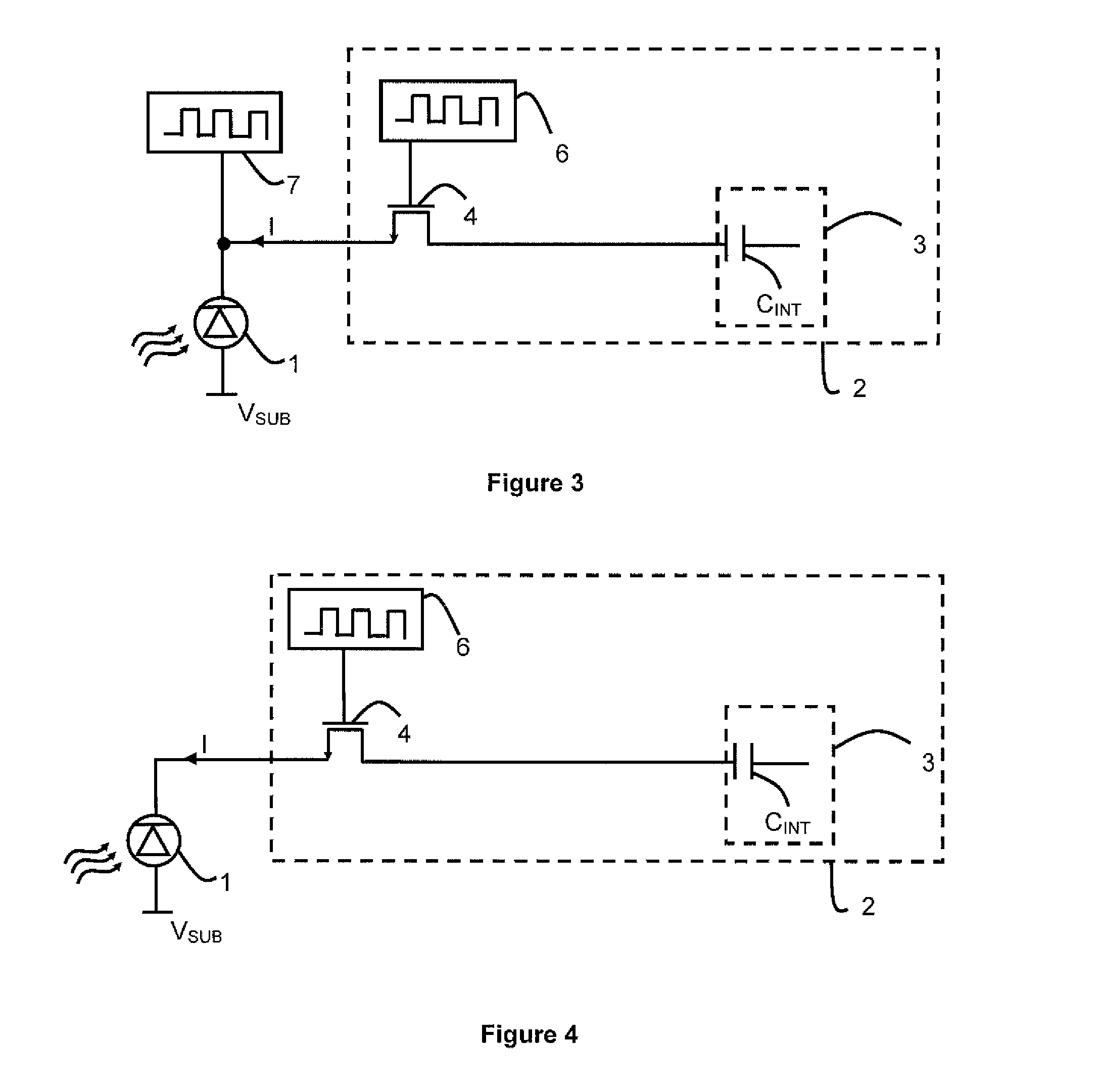
[0023]As illustrated in FIGS. 2 to 5, the detection circuit comprises a photodiode 1 connected to a readout circuit 2. The readout circuit comprises an integrator 3 storing the charges coming from the photodiode 1. The readout circuit 2 converts a current signal into a voltage signal. The integrator device 3 comprises an integration capacitor CINT. Advantageously, the photodiode 1 detects an infrared radiation.

[0024]The photodiode is advantageously made in a Type III-V substrate, for example, InP, GaAS, GaAlAs, or a type II-VI substrate for example HgCdTe.

[0025]According to the embodiments, the integrator 3 can be for example a direct injection device, a buffered direct injection device, a device of the type capacitive transimpedance amplifier or a simple integration capacitor CINT. Advantageously, the integrator 3 comprises means for resetting the charges stored in the integration capacitor CINT.

[0026]In a particular embodiment, the detection circuit comprises a switching circuit f...


PUM


Abstract

The detection circuit comprises a switch connected between a photodiode and an integrator. It further comprises means for alternately switching bias conditions of the photodiode between a reverse bias and another state. The electronic traps in the photodiode are regularly passivated during the other state.

Description

TECHNICAL FIELD OF THE INVENTION[0001]The invention concerns a detection circuit including a switch connected between a photodiode and an integrating circuit.[0002]The invention also concerns a method for operating such detection circuit.STATE OF THE ART[0003]As illustrated in FIG. 1, in conventional detection circuits, a photodiode 1, reversely biased, outputs a current representative of a scene observed. The photodiode 1 outputs this current, for a predefined duration, to a readout module 2 which includes an integrating device 3.[0004]The readout module 2 comprises an injection transistor 4 connected to the integrating device 3. An injection potential VBIAS is applied to the gate electrode of the injection transistor 4 and is used to bias the photodiode 1. Such a circuit is commonly called an ‘direct injection circuit’.[0005]The current provided by the photodiode 1 is processed by the readout circuit 2 in order to provide a bit of information about the scene observed.[0006]Theoret...

Claims


Application Information

Patent Timeline
IPC IPC(8): G01J1/44
CPCG01J1/44
Inventor RUBALDO, LAURENTRICARD, NICOLAS
Owner LYNRED
Why Eureka
Try Eureka