
Flow control apparatus for use in a wellbore

a flow control and wellbore technology, applied in the direction of drinking water installation, wellbore/well accessories, construction, etc., can solve the problems of only being able to adjust the apparatus at the well surface, reducing the production of oil, and affecting the operation of the wellbor

Inactive Publication Date: 2005-04-26
WEATHERFORD TECH HLDG LLC
View PDF26 Cites 89 Cited by
  • Summary
  • Abstract
  • Description
  • Claims
  • Application Information

AI Technical Summary

Benefits of technology

This patent describes an apparatus that allows for fluid communication within a tube-like structure. It includes two rings: one fixed and one rotating. When the rotating ring moves, it can align with the fixed ring to form a pathway for fluid movement. Additionally, there is a space connected to both the fixed and rotating rings where fluids can enter or exit the tube. Overall, this design helps enable smooth fluid transfer without obstructing the pipe's natural flow.

Problems solved by technology

The technical problem addressed in this patent is how to control the flow of fluids in a hydrocracking well. Current methods involve placing restrictions on the movement of fluids either through the use of fixed screens or by controlling the pressure in the wellbore. These limitations lead to reduced efficiencies and increased costs associated with producing oil from the well. This patent proposes an improved solution that allows remote regulation of the fluid flow into the wellbore, providing greater flexibility and better results.

Method used


Image

  • Flow control apparatus for use in a wellbore
  • Flow control apparatus for use in a wellbore
  • Flow control apparatus for use in a wellbore

Examples


Embodiment Construction

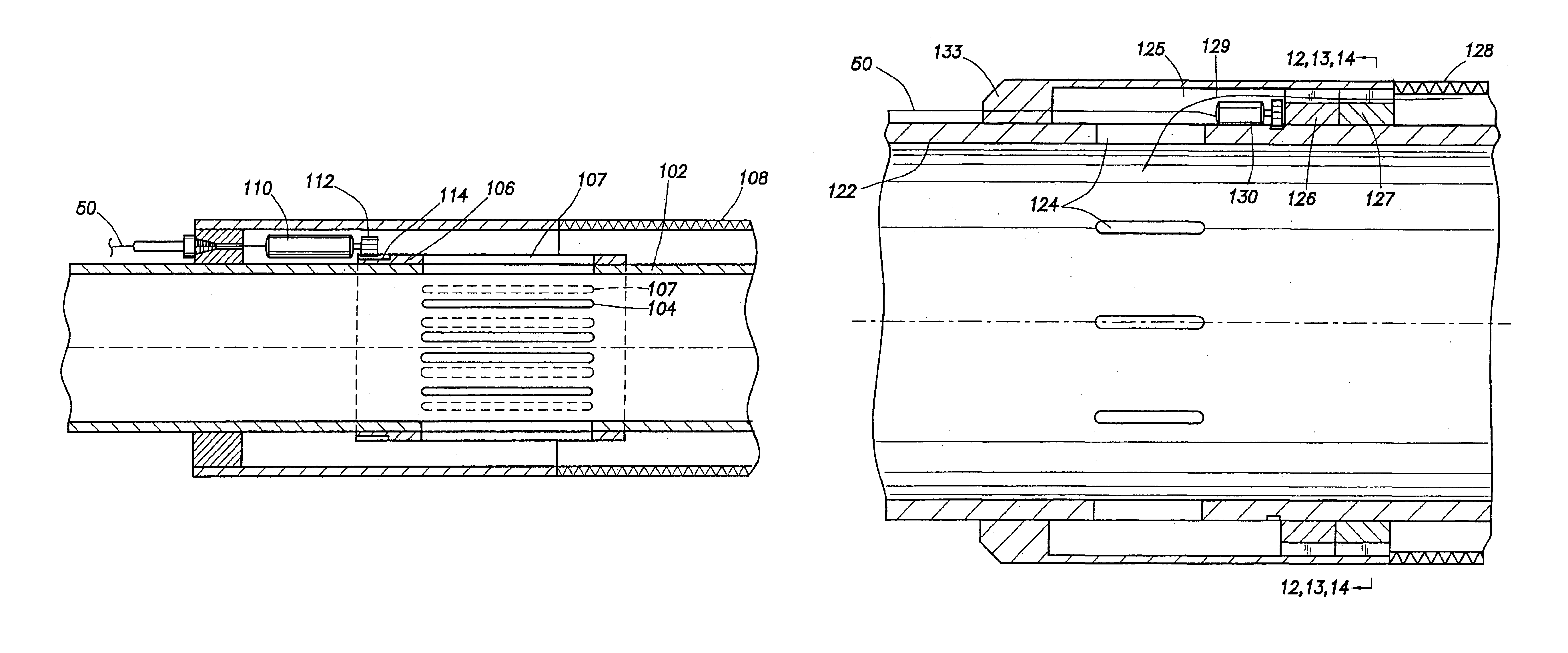
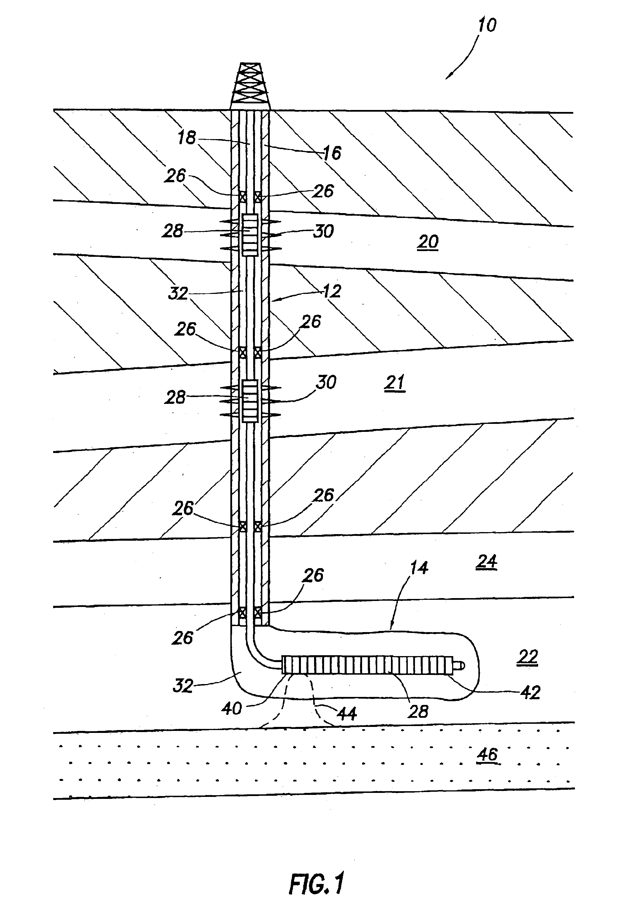
[0037]FIG. 3 shows a cross-sectional view of one embodiment of a plurality of flow control apparatuses 54-60 coupled to a string of tubing 18 run in a wellbore. Included is at least one control line 50 which runs from the surface 52 to the flow control apparatuses 54-60. The control line 50 may be disposed on the outer surface of the tubing 18 by clamps (not shown). The clamps may be adapted to cover and to protect the control line 50 on the tubing 18 during run-in and operation in the well.

[0038]In one embodiment, each flow control apparatus comprises a tubular member (FIG. 4) having apertures formed in a wall thereof. The apertures provide fluid communication between an outside and an inside of the tubular member. Each flow control apparatus further comprises a screen disposed radially outward of the tubular member. The control line 50 is adapted to individually or collectively set each flow control apparatus 54-60 in a first position or a second position to control a flow of flui...


PUM


Abstract

An apparatus and method of controlling the flow of hydrocarbons into and/or out of a string of tubing disposed in a wellbore. In one embodiment, the apparatus comprises a tubular member having at least one aperture formed in a wall thereof and a sleeve disposed radially outward of the tubular member. The sleeve is selectively movable between a first position and a second position to control the flow between the outside and the inside of the tubular member. In one aspect, the apparatus further comprises a biasing member disposed adjacent the sleeve and adapted to apply a force against the sleeve in an axial direction and further comprises a piston adapted to receive a hydraulic pressure to move the sleeve against the force of the biasing member. In another aspect, the apparatus further comprises a electromechanical device adapted to selectively move the sleeve between the first position and the second position and further comprises a control line adapted to conduct an electrical current. In another embodiment, the apparatus comprises a tubular member having at least one aperture formed therein and a fixed ring and a rotatable ring disposed radially outward of the tubular member. In still another embodiment, the apparatus comprises a plurality of annular ribs having an inner surface, at least one support rod disposed along the inner surface of the annular ribs, and at least one control line disposed along the inner surface of the annular ribs.

Description


Claims


Application Information

Patent Timeline
Owner WEATHERFORD TECH HLDG LLC
Features
  • Generate Ideas
  • Intellectual Property
  • Life Sciences
  • Materials
  • Tech Scout
  • Unparalleled Data Quality
  • Higher Quality Content
  • 60% Fewer Hallucinations
Learn More