Clamp

Inactive Publication Date: 2005-04-26
NIFCO INC +1
View PDF15 Cites 31 Cited by
  • Summary
  • Abstract
  • Description
  • Claims
  • Application Information

AI Technical Summary

Benefits of technology

[0018]In the third aspect of the invention, the holding piece has a thickness larger than that of the base portion, so that the stopper can elastically deform easily and, at the same time, the second rod-shaped member can be easily received.
[0019]According to the fourth aspect of the invention, only a single stopper projects from the i

Problems solved by technology

Therefore, there is a risk that the pipe is not sufficiently supported in a state that the clamp is fixed to a body panel.

Method used


Image

  • Clamp
  • Clamp
  • Clamp

Examples


Embodiment Construction

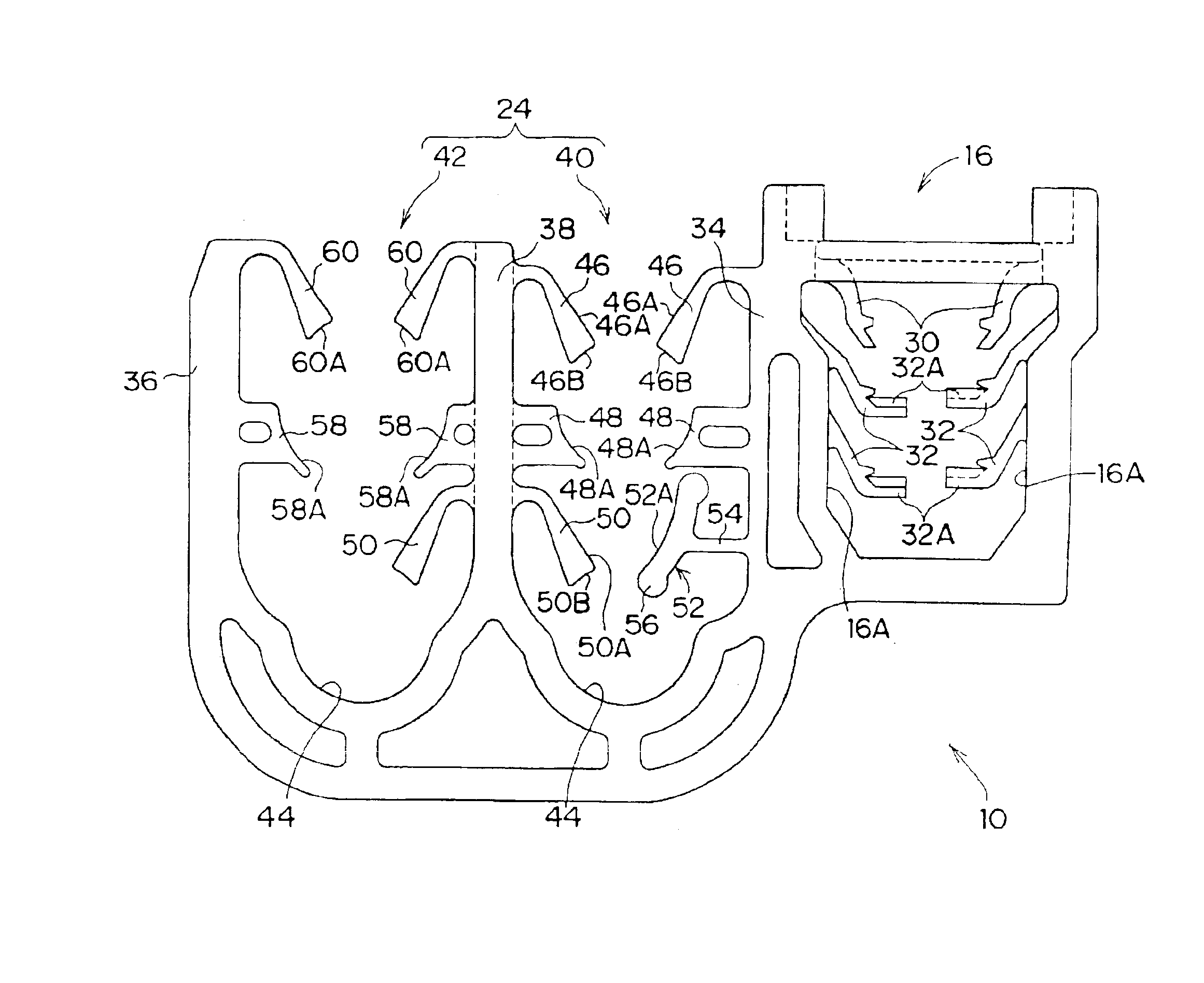
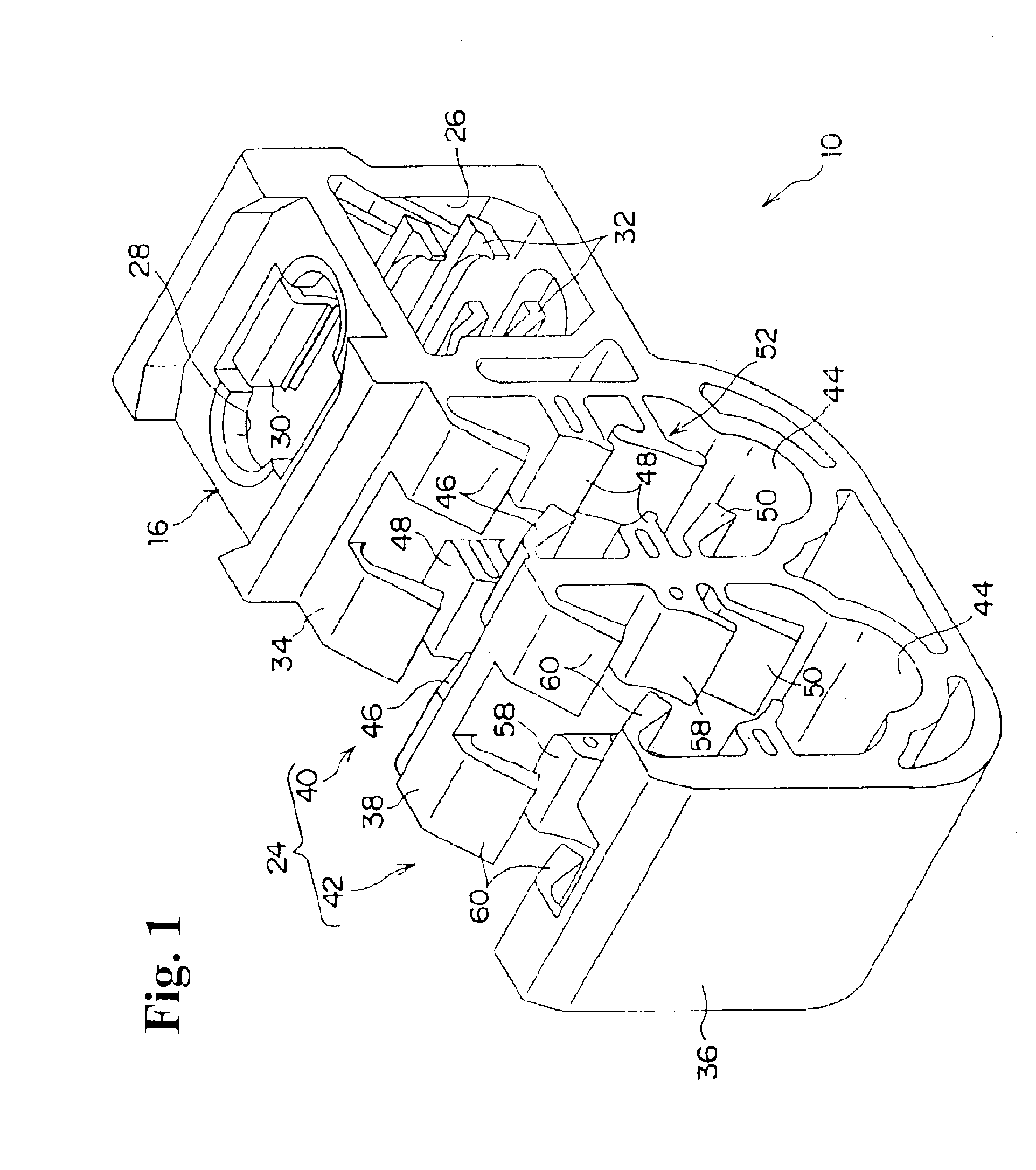
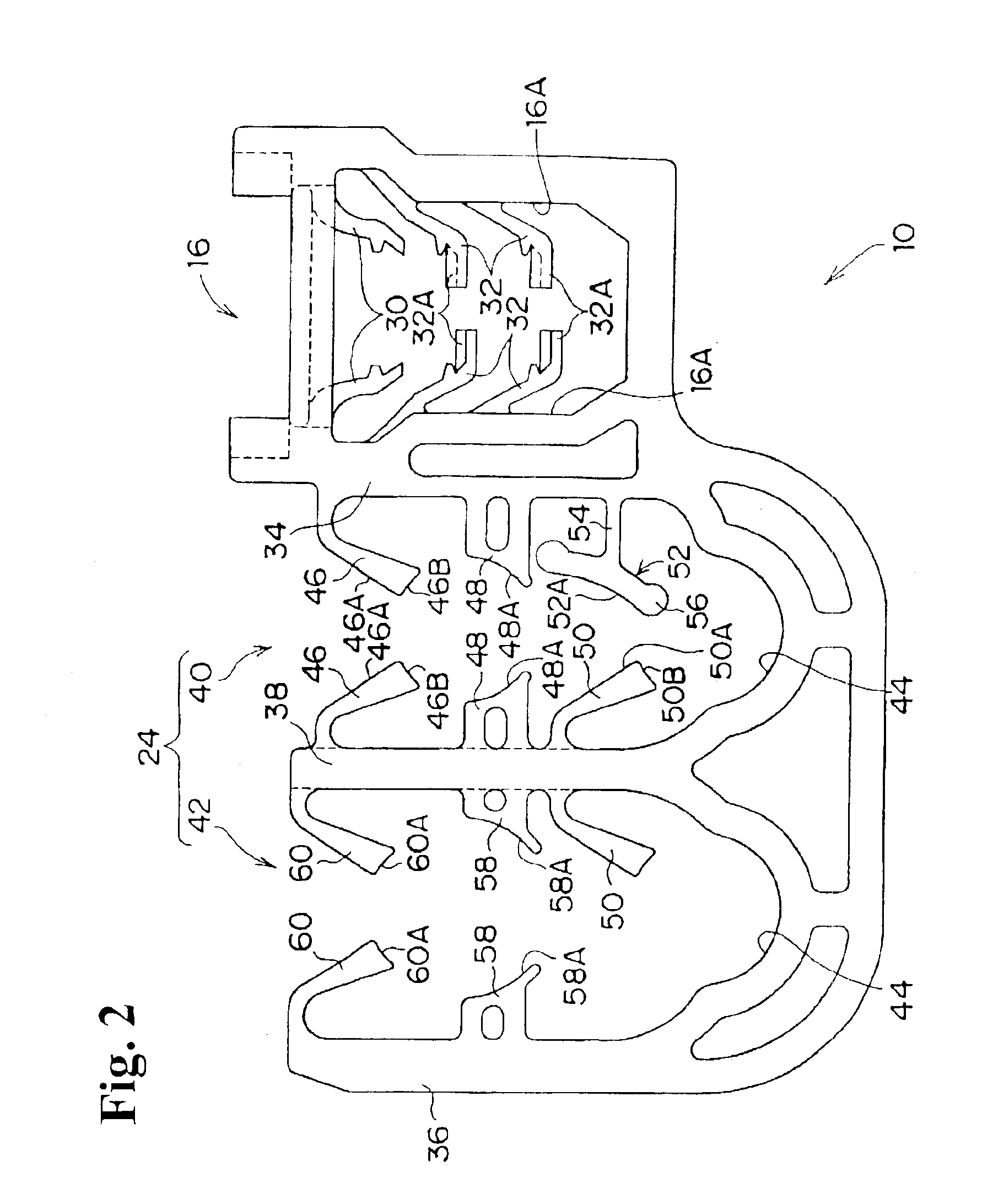
[0027]Hereunder, embodiments of the present invention will be explained with reference to the accompanying drawings. FIGS. 1 through 5 show a clamp 10 according to the present invention. The clamp 10 is formed of a fitting portion 16 to be fitted to a stud bolt 14 projecting from a body panel 12 of an automobile and a clamping portion 24 for holding pipes 18, 20, and 22 of an air conditioner as rod-shaped members.

[0028]The fitting portion 16 has a box shape with openings 26 on sidewalls. A hole 28 for inserting the stud bolt 14 projecting from the body panel 12 is provided on an upper portion of the fitting portion 16. A pair of guiding pieces 30 projects inwardly toward a lower side from the hole 28 for guiding the stud bolt 14 to a pair of stopping pieces 32.

[0029]The stopping pieces 32 are disposed at two positions on each of both inner walls 16A of the fitting portion 16 in the vertical direction, and forward ends thereof have horizontal surfaces. A space between the two stoppin...


PUM


Abstract

A clamp includes a fitting portion to be fixed to an object to be attached; a clamp portion having a substantially U-character shape connected to the fitting portion; a first receiving portion for receiving a rod-shaped member through an insertion port; and a second receiving portion for receiving a rod-shaped member through an insertion port of the clamp portion and passing through the first receiving portion. An elastic piece extends from an inner wall of the clamp portion to hold the first rod-shaped member together with the first receiving portion. A stopper extends from the inner wall of the clamp portion to hold the second rod-shaped member together with the second receiving portion and to prevent the first rod-shaped member from entering the second receiving portion.

Description

BACKGROUND OF THE INVENTION AND RELATED ART STATEMENT[0001]The invention relates to a clamp for attaching a pipe and the like of an air conditioner in an automobile to an object to be attached such as a body panel.[0002]Conventionally, a pipe of an air conditioner and the like is attached to a predetermined position of a body panel in an automobile through a clamp. For example, as shown in FIG. 6, Japanese Patent Publication (KOKAI) No. 2000-205211 has disclosed a clamp that includes a fitting portion 100 to be fitted to a stud bolt projecting from a body panel of an automobile and a clamp portion 106 for holding pipes 102, 104.[0003]Circular arc shape holders 108, 110 corresponding to outer diameters of the pipes 102, 104 are formed on the clamp portion 106. Supporting walls 112, 114 are provided to the respective holders 108, 110. Elastically deformable guiding pieces 116, 118, which bend toward central portions of the respective holders 108, 110, extend from forward end surfaces ...

Claims


Application Information

Patent Timeline
IPC IPC(8): F16L3/22F16L3/12F16L3/223
CPCB60R16/0215F16L3/223F16L3/1203
Inventor MIURA, HIDEYAKAWAKAMI, YASUAKI
Owner NIFCO INC
Why Eureka
Try Eureka