Thin film deposition reactor

Active Publication Date: 2005-04-26
WONIK IPS CO LTD
View PDF15 Cites 18 Cited by
  • Summary
  • Abstract
  • Description
  • Claims
  • Application Information

AI Technical Summary

Benefits of technology

[0006]The present invention provides a thin film deposition reactor with an improved exhaust structure, which can effectively exhau

Problems solved by technology

Also, an excellent exhaust structure is required since remaining byproduct gases may a

Method used


Image

  • Thin film deposition reactor
  • Thin film deposition reactor
  • Thin film deposition reactor

Examples


Embodiment Construction

[0017]The present invention will now be described more fully with reference to the accompanying drawings, in which exemplary embodiments of the invention are shown.

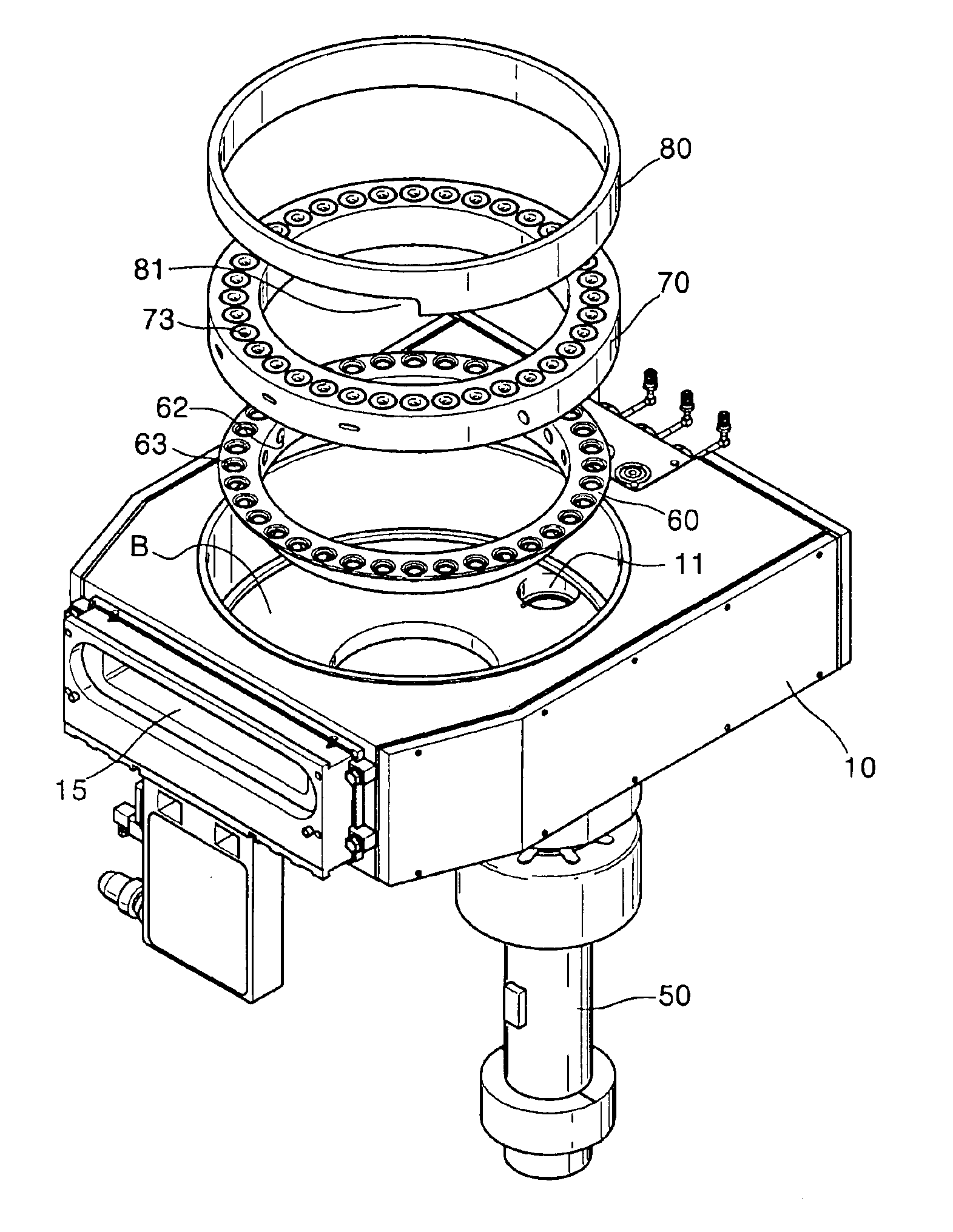
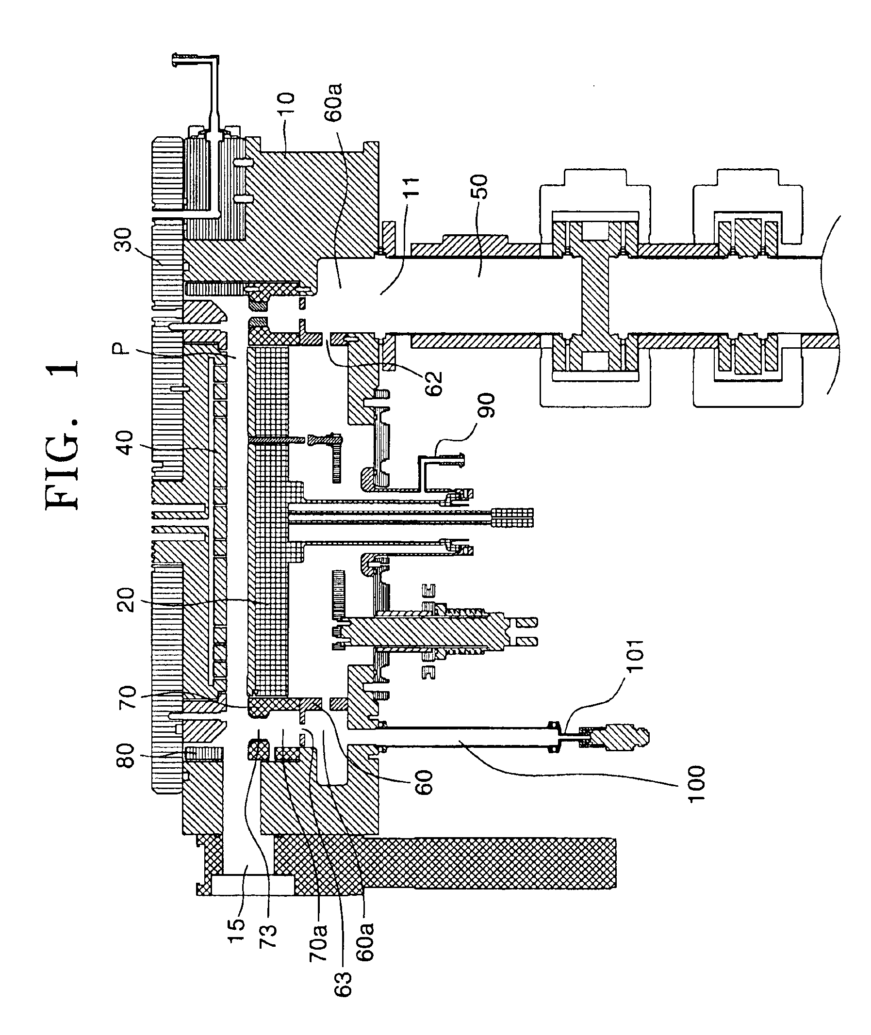
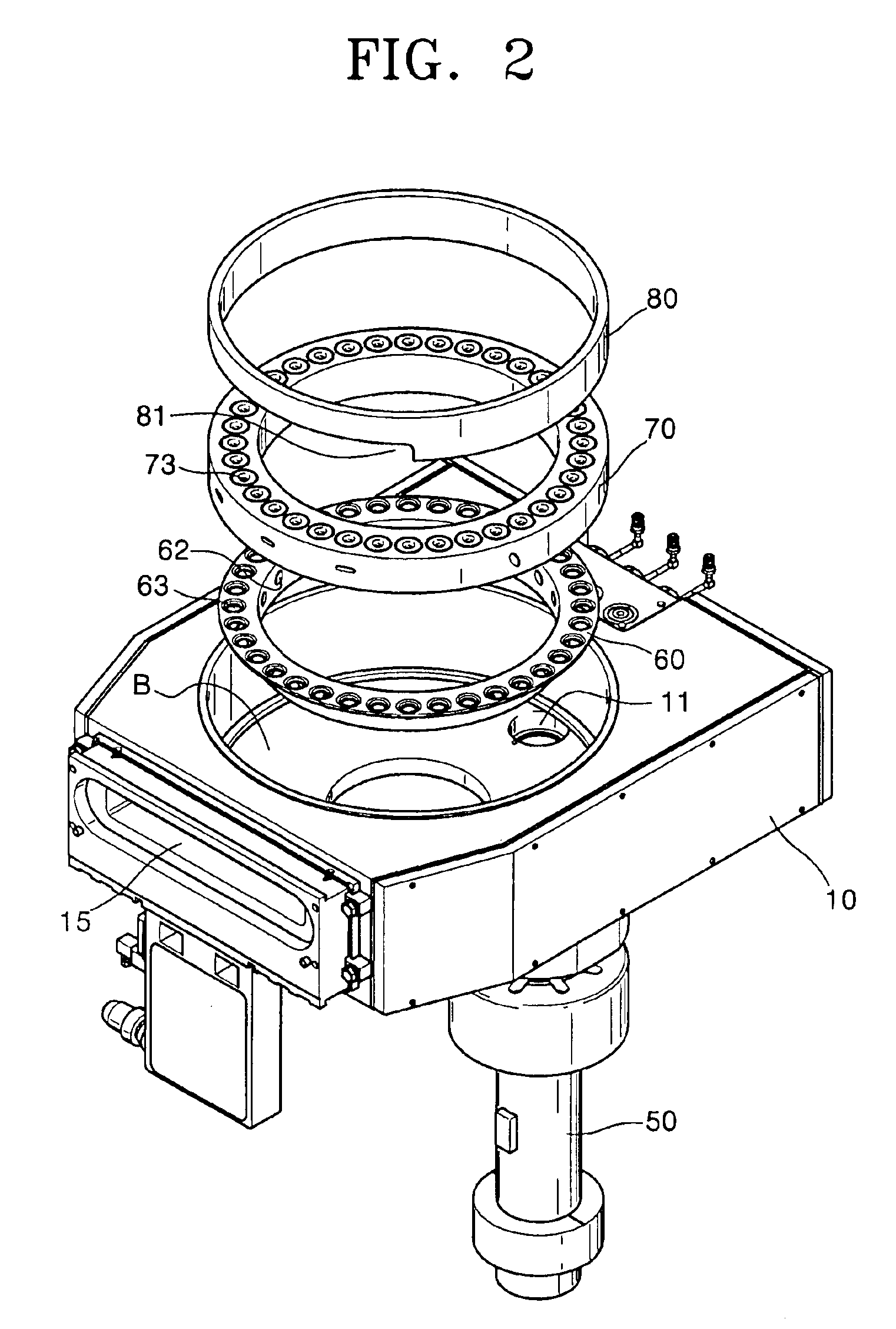
[0018]FIG. 1 is a cross-sectional view of a thin film deposition reactor according to the present invention, FIG. 2 is a perspective view of a stack of a lower pumping baffle, an upper pumping baffle, and a chamber insertion shown in FIG. 1, FIG. 3 is a detailed perspective view of the lower pumping baffle shown in FIG. 2, FIG. 4 is a partial perspective view of a stack of the upper pumping baffle and the chamber insertion shown in FIG. 2, and FIG. 5 is a perspective view of a thin film deposition reactor of FIG. 1.

[0019]Referring to FIG. 1, a thin film deposition reactor comprises a reactor block 10, a wafer block 20, a top lid 30, a showerhead 40, and an exhaust line 50. The reactor block 10 includes a deposition space P, and the wafer block 20, where a wafer W is mounted, is disposed in the reactor block 10. The top li...


PUM

PropertyMeasurementUnit
Circumferenceaaaaaaaaaa

Abstract

Provided is a thin film deposition reactor, including a reactor block having a deposition space, a wafer block, a top lid for covering and sealing the reactor block, a showerhead for spraying a reaction gas on the wafer block, and an exhaust line through which gases are exhausted from the reactor block. A lower pumping baffle and an upper pumping baffle are stacked on a bottom of the reactor block between an outer circumference of the wafer block and an inner circumference of the reactor block. A lower pumping region is formed between the lower pumping baffle and an inner sidewall of the reactor block. An upper pumping region is formed between the upper pumping baffle and the inner sidewall of the reactor block. The deposition space is connected to the upper pumping region by a plurality of upper pumping holes formed in the upper pumping baffle, and the upper pumping region is connected to the lower pumping region by a plurality of lower pumping holes formed in the lower pumping baffle. The lower pumping region is connected to the exhaust line.

Description

[0001]This application claims the priority of Korean Patent Application No. 2003-19960, filed on Mar. 31, 2003, in the Korean Intellectual Property Office, the disclosure of which is incorporated herein by reference in its entirety.BACKGROUND OF THE INVENTION[0002]1. Field of the Invention[0003]The present invention relates to a thin film deposition reactor with an improved exhaust structure.[0004]2. Description of the Related Art[0005]Different reaction gases are simultaneously or alternately sprayed on a wafer loaded in a conventional reactor to form a thin film on the wafer, such that the thin film contains few impurities and has excellent electrical characteristics and a uniform thickness. As the number of processed wafers increases, while a thin film is being deposited on a wafer, the accumulation of powder in the reactor should be minimized. Also, an excellent exhaust structure is required since remaining byproduct gases may adversely affect deposition of a thin film on a subs...

Claims


Application Information

Patent Timeline
IPC IPC(8): C23C16/44H01L21/20
CPCH01L21/6719C23C16/4412H01L21/20
Inventor PARK, YOUNG HOONBAIK, CHOON KUMLIM, HONG JOOCHANG, HO SEUNG
Owner WONIK IPS CO LTD
Why Eureka
Try Eureka