Automatically loadable and blade-stabilizing utility knife

a technology of automatic loading and blade stabilization, which is applied in the field of knives, can solve the problems of user still needing to change the direction of the blade, user is still easy to get hurt the user is still easily injured when replacing the blade, so as to achieve the effect of easy, true and safe loading

Inactive Publication Date: 2005-05-03
CHIH GORDON
View PDF8 Cites 53 Cited by
  • Summary
  • Abstract
  • Description
  • Claims
  • Application Information

AI Technical Summary

Benefits of technology

[0015]It is therefore a primary object of the present invention to provide a knife. The blades can be easily, truly and safely loaded into the housing of the knife.
[0016]It is a further object of the present invention to provide the above knife in which the blade can be more smoothly pushed and more reliably used.
[0017]It is still a further object of the present invention to provide the above knife which has simple structure and components for easily truly engaging with the blade.
[0018]It is still a further object of the present invention to provide the above knife which can be easily and firmly assembled to lower the manufacturing cost.
[0019]According to the above objects, the automatically loadable and blade-stabilizing utility knife includes a handheld housing, a slidable pushing mechanism, a resilient section, a releasing mechanism and a receptacle section. The housing has an open front end and an open rear end. The receptacle section is disposed in the housing between the front and rear ends. A pair of guide rails are disposed in the housing. A slide block is disposed on the pushing mechanism between the guide rails, whereby the blade can be more stably loaded and used.

Problems solved by technology

It is troublesome and apt to get hurt to replace the blade.
However, a user still needs to change the direction of the blade or replace the blade with hands.
Therefore, the user is still easy to get hurt when replacing the blade.
This is inconvenient in use.
For example, in the case that no spare blade is available, it is impossible to further use the utility knife.
However, it is still necessary for a user to open the housing and replace the blade with hands.
Also, it is troublesome and uneasy to operate such utility knife.
In addition, the manufacturing cost for such utility knife is relatively high.2. The spherical blade rest seat leads to enlarged handle of the utility knife.
Especially when cutting a caplet, the blade is very apt to break.
Therefore, such utility knife is not popular after released.
This leads to malfunction of the utility knife.
It is uneasy to assemble so small components of the utility knife.
This will lead to malfunction of the utility knife.
Therefore, the blade 93 can be hardly smoothly fed.
As a result, the structure is unstable and when using the utility knife, the blade 93 is apt to swing.

Method used


Image

  • Automatically loadable and blade-stabilizing utility knife
  • Automatically loadable and blade-stabilizing utility knife
  • Automatically loadable and blade-stabilizing utility knife

Examples


Embodiment Construction

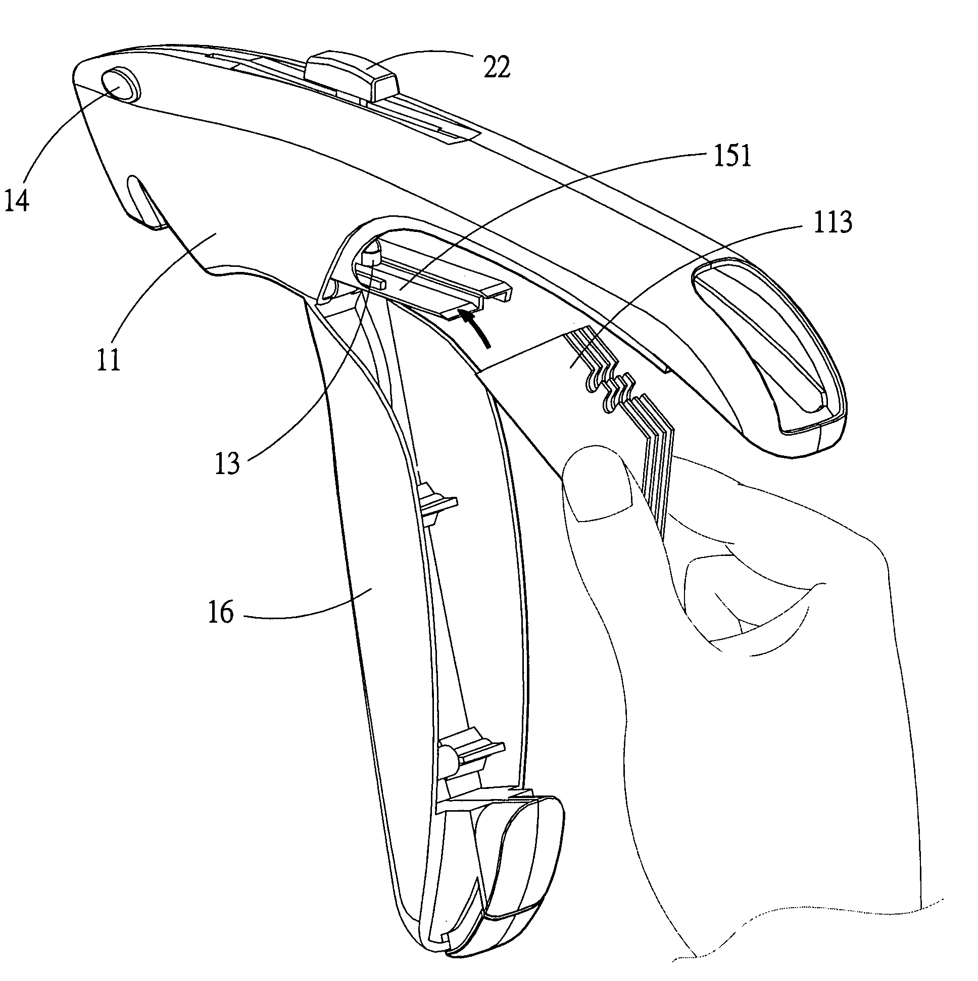
[0039]Please refer to FIGS. 5 to 13. The automatically loadable and blade-stabilizing utility knife 1 of the present invention includes a handheld housing 11, a slidable pushing mechanism 12, a resilient section 13, a releasing mechanism 14 and a receptacle section 15.

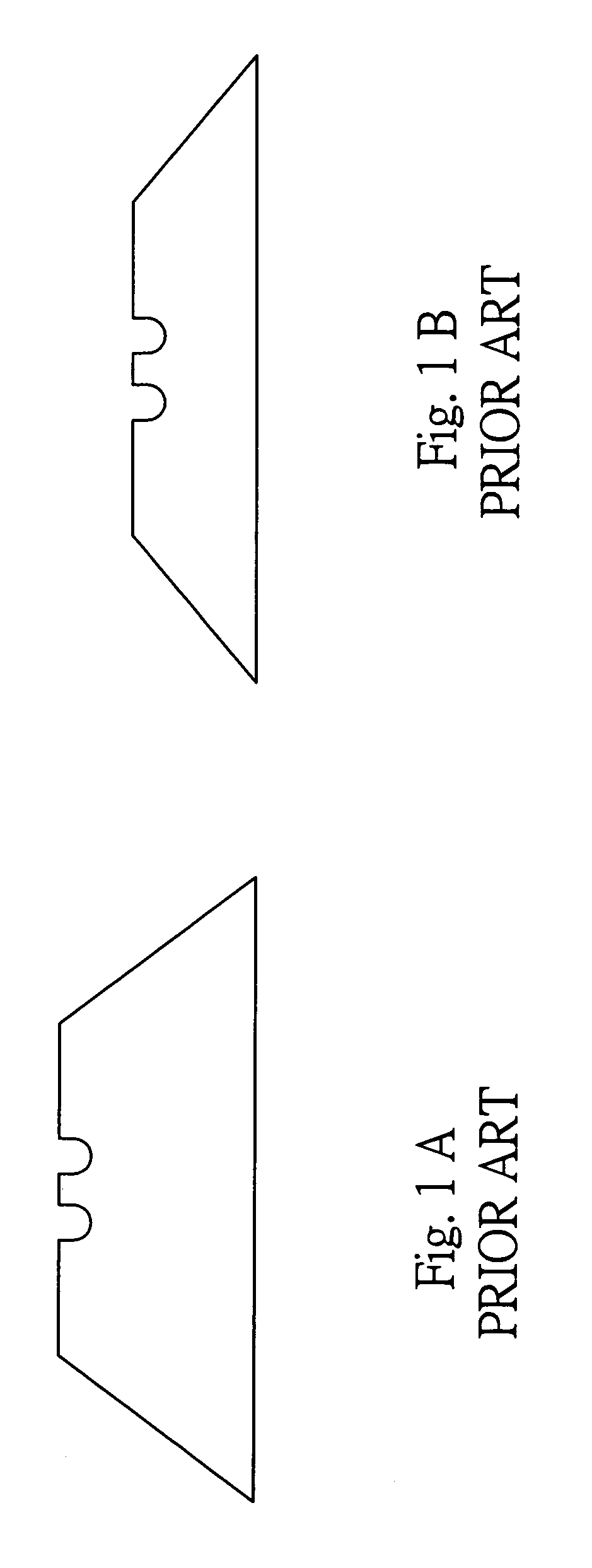
[0040]The housing 11 has a front end 111 and a rear end 112. Several blades 113 can be accommodated in the housing 11. Each blade 113 has a notched section 113′. Each of the front and rear ends 111, 112 has an opening. The blades 113 are loaded into the housing through the opening of the rear end 112. A restricting section 114 such as a leaf spring is disposed at the rear end 112 for preventing the blades 113 from slipping out of the rear end 112.

[0041]The pushing mechanism 12 is disposed on the housing 11, including an activating section 22 and a moving section 24.

[0042]The activating section 22 outward protrudes from the housing 11 and is manually movable between the front end 111 and the rear end 112. In addition, ...


PUM


Abstract

An automatically loadable and blade-stabilizing utility knife including a handheld housing, a slidable pushing mechanism, a resilient section, a releasing mechanism and a receptacle section. The housing has an open front end and an open rear end and serves to accommodate several blades therein. The pushing mechanism serves to engage with and push one of the blades. The resilient section serves to push the blades. The releasing mechanism serves to release the blade from the pushing mechanism. The receptacle section is disposed in the housing between the front and rear ends. The overlapping blades are loaded into the receptacle section through the opening of the rear end. Only one of the blades is permitted to slide between the front and rear ends. A pair of guide rails are disposed in the housing. A slide block is disposed on the pushing mechanism between the guide rails, whereby the blade can be more stably loaded and used.

Description

BACKGROUND OF THE INVENTION[0001]The present invention is related to a knife as a hand tool, and more particularly to an automatically loadable and blade-stabilizing utility knife.[0002]The conventional utility knifes as hand tools have been developed by several stages.[0003]The early utility knife has a housing composed of two substantially symmetrical casings locked together by screws. A blade is accommodated in the housing. The housing has an opening at front end and is equipped with a driving unit for pushing the blade to protrude from the front end and pulling the blade back into the housing. When the blade is worn out, a user must unscrew the screws to open the housing for changing the direction of the blade or replacing the blade. It is troublesome and apt to get hurt to replace the blade.[0004]An improved utility knife has a hooking unit disposed between the two casings for easily opening the housing. However, a user still needs to change the direction of the blade or replac...

Claims


Application Information

Patent Timeline
Patent Type & Authority Patents(United States)
IPC IPC(8): B26B5/00
CPCB26B5/001
Inventor CHIH, GORDON
Owner CHIH GORDON
Why Eureka
Try Eureka