Electromotive can opener

a technology of electric motors and can openers, applied in applications, liquid handling, transportation and packaging, etc., can solve the problems of uneasy and inconvenient operation, knife sliding out, and the need for a larger operating force of can openers, and achieve the effect of high twisting for

Inactive Publication Date: 2005-05-03
LEE HUI LING
View PDF5 Cites 19 Cited by
  • Summary
  • Abstract
  • Description
  • Claims
  • Application Information

AI Technical Summary

Benefits of technology

[0003]Accordingly, the primary object of the present invention is to provide an electromotive can opener which comprises a body. The body is formed by a first half and a second half. A motor, a touch switch for actuating the motor, a high twisting gear set, and a cutter handle are assembled to the body. In the high twisting gear set, a plurality of following gears and driving gear are engaged one by one and then is engaged to a driven shaft. The driven shaft is assembled with a driving gear. A knife protrudes out of a cutter handle. In operation, the knife cuts into the can and the touch switch is pressed by the cutter handle to actuate the motor and the shaft is driven. The can is driven to rotate to be cut along the periphery by the knife; and high twisting gear set formed by the plurality of gears provides a high twisting force for securing the can firmly.

Problems solved by technology

However, the prior art openers need a larger force for operating it and it is possible that the knife will slide out from the can body.
The operation is uneasy and inconvenient.

Method used


Image

  • Electromotive can opener
  • Electromotive can opener
  • Electromotive can opener

Examples


Embodiment Construction

[0009]In order-that those skilled in the art can further understand the present invention, a description will be described in the following in details. However, these descriptions and the appended drawings are only used to cause those skilled in the art to understand the objects, features, and characteristics of the present invention, but not to be used to confine the scope and spirit of the present invention defined in the appended claims.

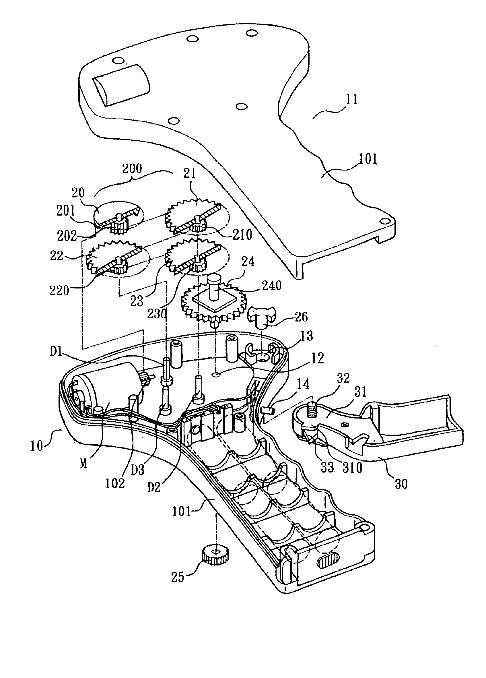
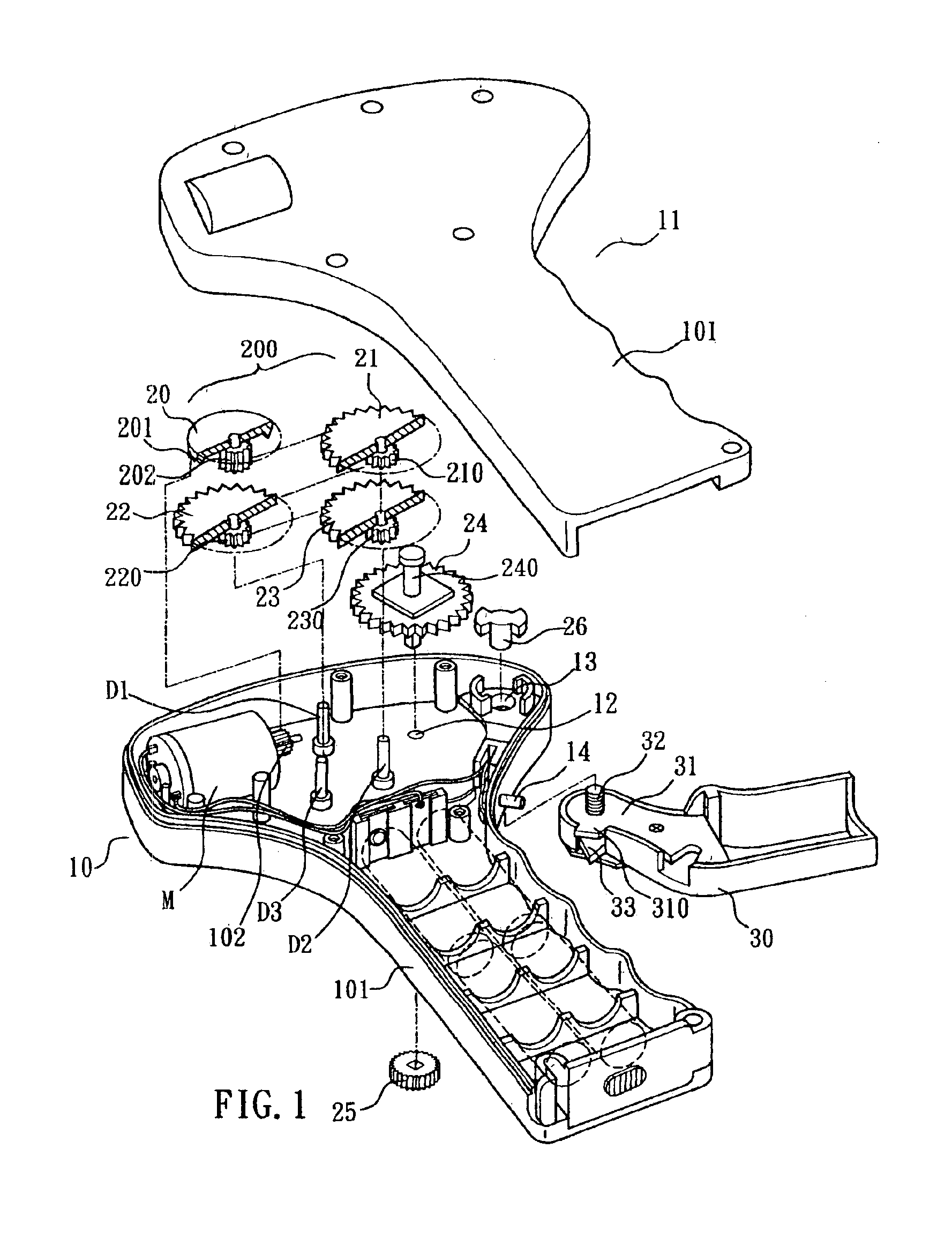
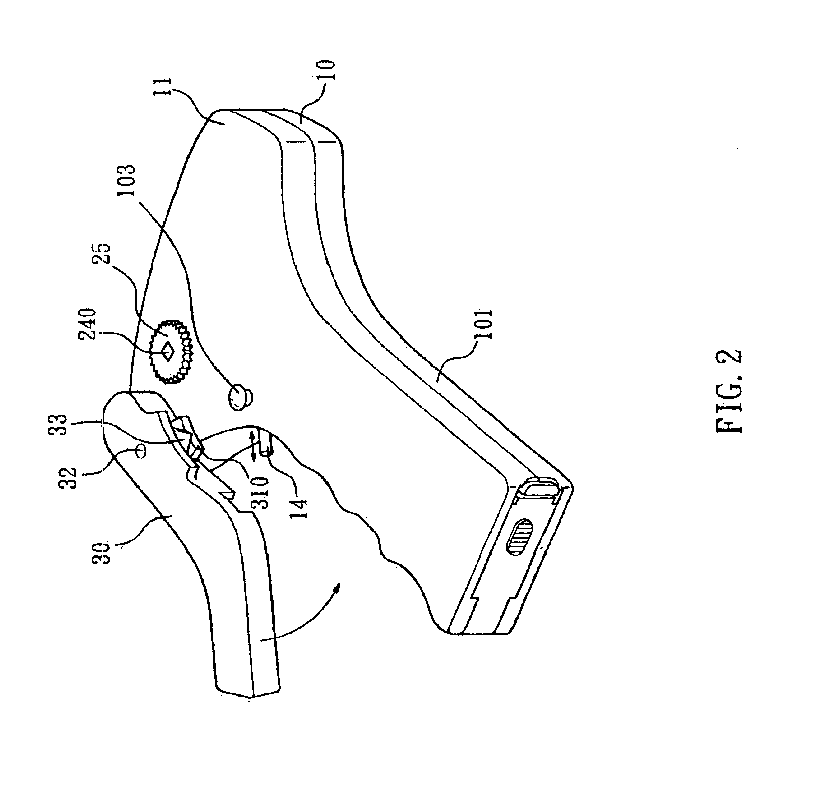
[0010]With reference to FIGS. 1, 2, 3 and 4, the electromotive can opener of the present invention includes a body which is formed by a first half 10 and a second half 11. A motor M, a touch switch 14 for actuating the motor, a high twisting gear set 200, and a cutter handle 30 are assembled to the body.

[0011]The body formed by the first half 10 and second half 11 has a body handle 101. The body handle 101 is formed with a space for receiving a battery set (not shown) for enabling the motor M. The first half 10 has a via hole 12, an axial hole 13,...


PUM


Abstract

An electromotive can opener comprises a body. The body is formed by a first half and a second half. A motor, a touch switch for actuating the motor, a high twisting gear set, and a cutter handle are assembled to the body. In the high twisting gear set, a plurality of following gears and driving gear are engaged one by one and then is engaged to a driven shaft. The driven shaft is assembled with a driving gear. A knife protrudes out of a cutter handle. In operation, the knife cuts into the can and the touch switch is pressed by the cutter handle to actuate the motor and the shaft is driven. The can is driven to rotate to be cut along the periphery by the knife; and high twisting gear set formed by the plurality of gears provides a high twisting force for securing the can firmly.

Description

FIELD OF THE INVENTION[0001]The present invention relates to can openers, and particular to an electromotive can opener which is operated electrically so that the user can open a can easily with only a small force by using the electromotive can opener.BACKGROUND OF THE INVENTION[0002]In the prior art, a can opener is operated manually, namely, an opener with a knife is held by the hand. The knife is cut into the can body firstly and then the knife moves along the periphery of the can body so as to open the can. However, the prior art openers need a larger force for operating it and it is possible that the knife will slide out from the can body. The operation is uneasy and inconvenient.SUMMARY OF THE INVENTION[0003]Accordingly, the primary object of the present invention is to provide an electromotive can opener which comprises a body. The body is formed by a first half and a second half. A motor, a touch switch for actuating the motor, a high twisting gear set, and a cutter handle a...

Claims


Application Information

Patent Timeline
Patent Type & Authority Patents(United States)
IPC IPC(8): B67B7/00B67B7/46B67B7/74B67B7/70B67B7/76
CPCB67B7/385
Inventor LEE, HUI LING
Owner LEE HUI LING
Why Eureka
Try Eureka