RAM air parachute with multistage deployment

a parachute and multi-stage technology, applied in the field of parachutes, can solve the problems of slowed, more ordered opening, and partial opening of the canopy, and achieve the effect of increasing the flow of air and inflated more slowly

Inactive Publication Date: 2005-05-03
ATAIR AEROSPACE +1
View PDF8 Cites 7 Cited by
  • Summary
  • Abstract
  • Description
  • Claims
  • Application Information

AI Technical Summary

Benefits of technology

[0011]The present invention substantially overcomes the deficiencies of the prior art through a canopy having multistage deployment. According to one aspect of the present invention, the conductance of cross porting in the ribs of the canopy is restricted at certain locations to control the inflation of the canopy. In particular, a canopy of the present invention has a first set of ribs with a first cross porting structure and a second set of ribs with a second cross porting structure. The first cross porting structure allows greater flow of air from one cell to an adjacent cell. The second cross porting structure limits airflow. Thus, upon deployment, cells connected with the second cross porting structure are inflated more slowly. The pilot experiences lower opening forces at several different times until the canopy is fully deployed. Furthermore, the partial opening of the canopy slows decent before the subsequent stages occur. According to another aspect of the invention, a nine (9) cell canopy opens in two (2) stages consisting of the center three (3) cells in a first stage and the outer six (6) cells in a second stage.
[0012]According to another aspect of the invention, a canopy of the present invention includes cross porting in ribs which varies over the entire span of the canopy. The conductance of the cross-ports are reduced from the center cell towards the end cells by reducing the cross-port area in subsequent ribs. Deployment of a canopy with such cross porting results in a slowed and more ordered opening. The inner cells open first, which slows decent, followed by adjacent cells till the end cells. The pilot experiences lower opening force over the time period of the delayed opening.
[0013]According to another aspect of the invention, a canopy of the present invention can maintain a straight leading edge through deployment. The center cell will inflate first and as the remaining cells inflate in sequence the leading edge unrolls from the center towards the end cells.
[0014]According to another aspect of the invention, a canopy of the present invention allows safer higher speed deployments. By restricting inlet air from the center cells a canopy is created that has far less spreading force to push the slider down. Therefore at higher speeds the aerodynamic force holding the slider up is greater than the slider force pushing it down. The slider is effectively prevented from coming down the lines until the center inflated cells decelerate the speed. As opposed to prior art canopies that will open faster at higher speeds, the inventive canopy can open slower with increasing speed over a particular design range. With the inventive canopy peak opening forces have been measured in the six to eight (6-8) g range at speeds up to two hundred fifty-six (256) mph. Where as prior art canopies have been recorded at over fifty (50) g at speeds of only one hundred fifty (150) mph. A six (6) g opening is soft and almost unnoticeable, ten (10) g's is painful, over thirteen (13) g's you begin to see injuries, i.e. spinal fractures in the neck.

Problems solved by technology

Furthermore, the partial opening of the canopy slows decent before the subsequent stages occur.
Deployment of a canopy with such cross porting results in a slowed and more ordered opening.

Method used


Image

  • RAM air parachute with multistage deployment
  • RAM air parachute with multistage deployment
  • RAM air parachute with multistage deployment

Examples


Embodiment Construction

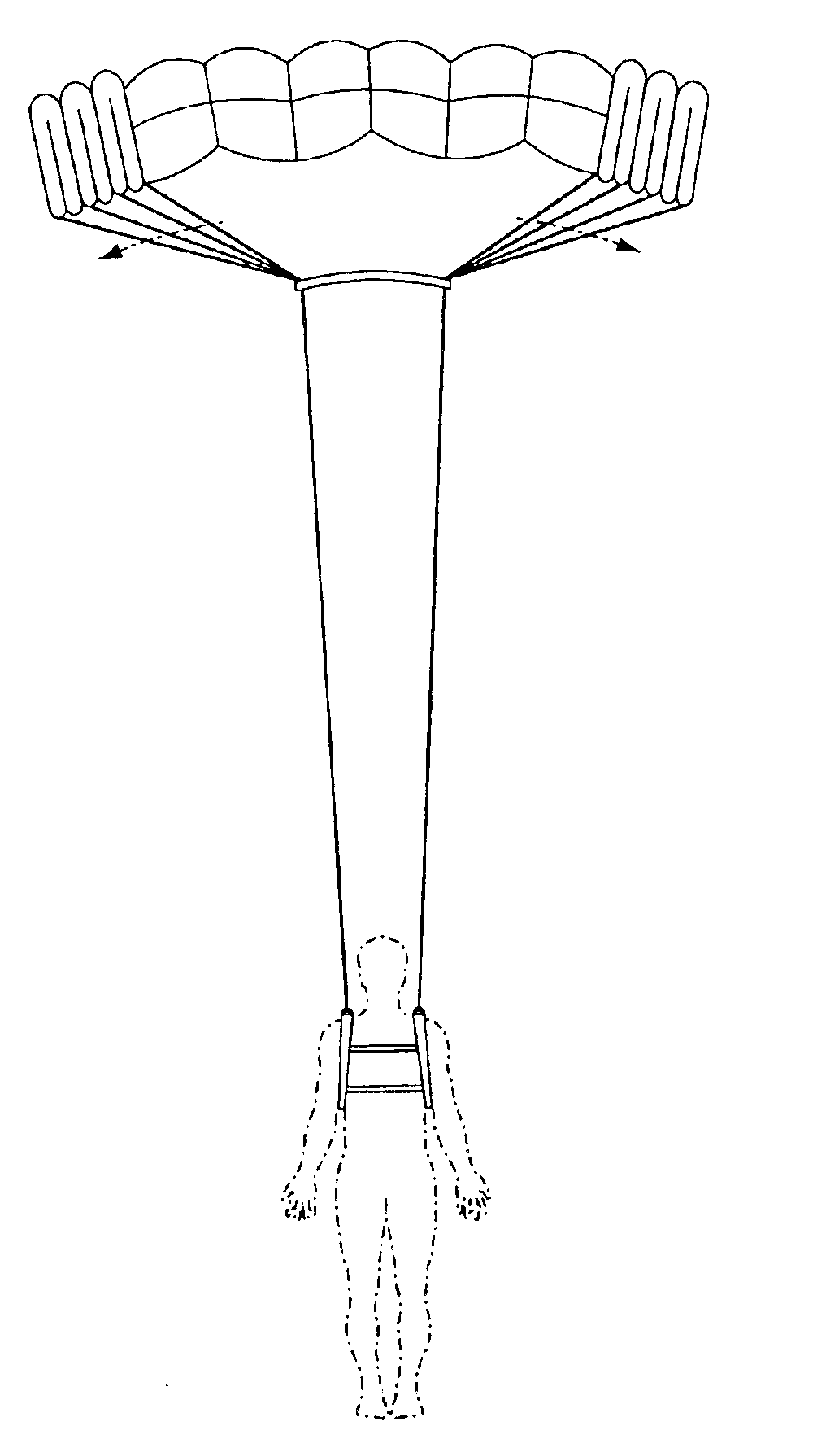
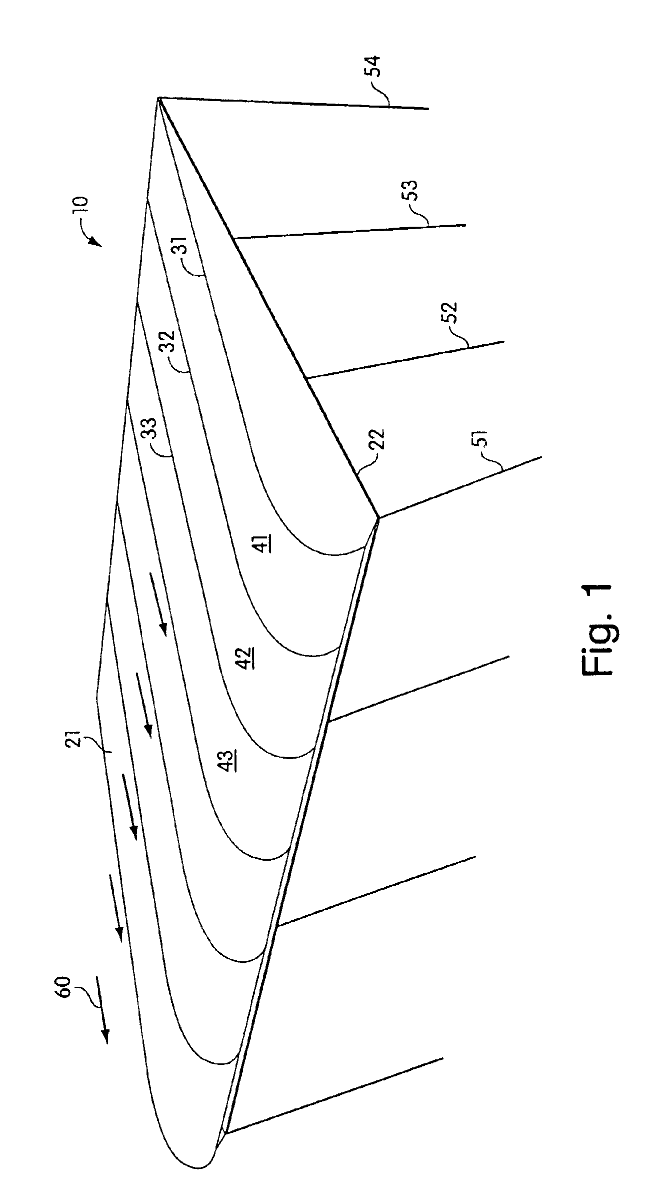
[0022]FIG. 1 illustrates a canopy of a ram air parachute 10 according to an embodiment of the present invention. The ram air parachute 10 includes a top skin 21 and bottom skin 22. A plurality of vertical ribs 31, 32, 33 are formed between the top skin 21 and the bottom skin 22 forming a plurality of cells 41, 42, 43. Typically, ram air parachutes to which the present invention applies have seven (7) or nine (9) cells. However, any number of cells can be used in connection with the present invention. Suspension lines 51, 52, 53, 54 are attached to at least some of the plurality of ribs. Not all of the suspension lines are shown in FIG. 1. Generally, suspension lines are attached to every other rib in the ram air parachute. The suspension lines are connected together to provide proper suspension of the user below the canopy and maintain the structure and the orientation of the canopy with respect to the pilot. FIG. 1 illustrates an elliptical canopy, but any shape canopy could be use...


PUM


Abstract

A ram air parachute of the present invention includes specific cross porting of the ribs between certain cells to create a two-stage or multi-stage deployment. Cross ports between certain sets of cells have reduced or no conductance. In this manner, the center cells of the canopy open first, slowing decent, before the outer cells. The staged deployment reduces the opening forces on the pilot particularly in high speed flights.

Description

[0001]This application claims priority to U.S. Provisional Application Ser. No. 60 / 340,910, filed Dec. 7, 2001.BACKGROUND OF THE INVENTION[0002]1. Field of the Invention[0003]The invention relates to generally to parachutes and more particularly to ram air parachutes having an improved canopy design providing reduced opening forces.[0004]2. Discussion of Related Art[0005]Parachutes have evolved over the years into highly sophisticated systems, and often include features that improve the safety, maneuverability, and overall reliability of the parachutes. Initially, parachutes included a round canopy. A skydiver was connected to the canopy via a harness / container to suspension lines disposed around the periphery of the canopy. Such parachutes severely lacked control. The user was driven about by winds with little mechanism for altering direction. Furthermore, such parachutes had a single descent rate based upon the size of the canopy and the weight of the parachutist. They could not g...

Claims


Application Information

Patent Timeline
Patent Type & Authority Patents(United States)
IPC IPC(8): B64D17/62B64D17/00B64D17/02
CPCB64D17/62B64D17/025
Inventor PRESTON, DANIEL
Owner ATAIR AEROSPACE
Why Eureka
Try Eureka