Synchronizing mechanism for correlated seat/backrest motion of an office chair

Inactive Publication Date: 2005-05-03
BOCK 1
View PDF10 Cites 28 Cited by
  • Summary
  • Abstract
  • Description
  • Claims
  • Application Information

AI Technical Summary

Benefits of technology

[0014]Proceeding from the prior art problems, it is an object of the invention to improve a synchronizing mechanism of the generic t

Problems solved by technology

A frequent problem in prior art synchronizing mechanisms resides in the pivoting angle of the backrest which is often rather restricted.
Moreover, very often the lowering motion of the seat panel is not sufficiently great even with a comparatively great pivoting angle of the backrest, which is due to the pivotable mounting of the seat and backrest carrier in a single joint on the base carrier.
Individually varying

Method used


Image

  • Synchronizing mechanism for correlated seat/backrest motion of an office chair
  • Synchronizing mechanism for correlated seat/backrest motion of an office chair
  • Synchronizing mechanism for correlated seat/backrest motion of an office chair

Examples


Embodiment Construction

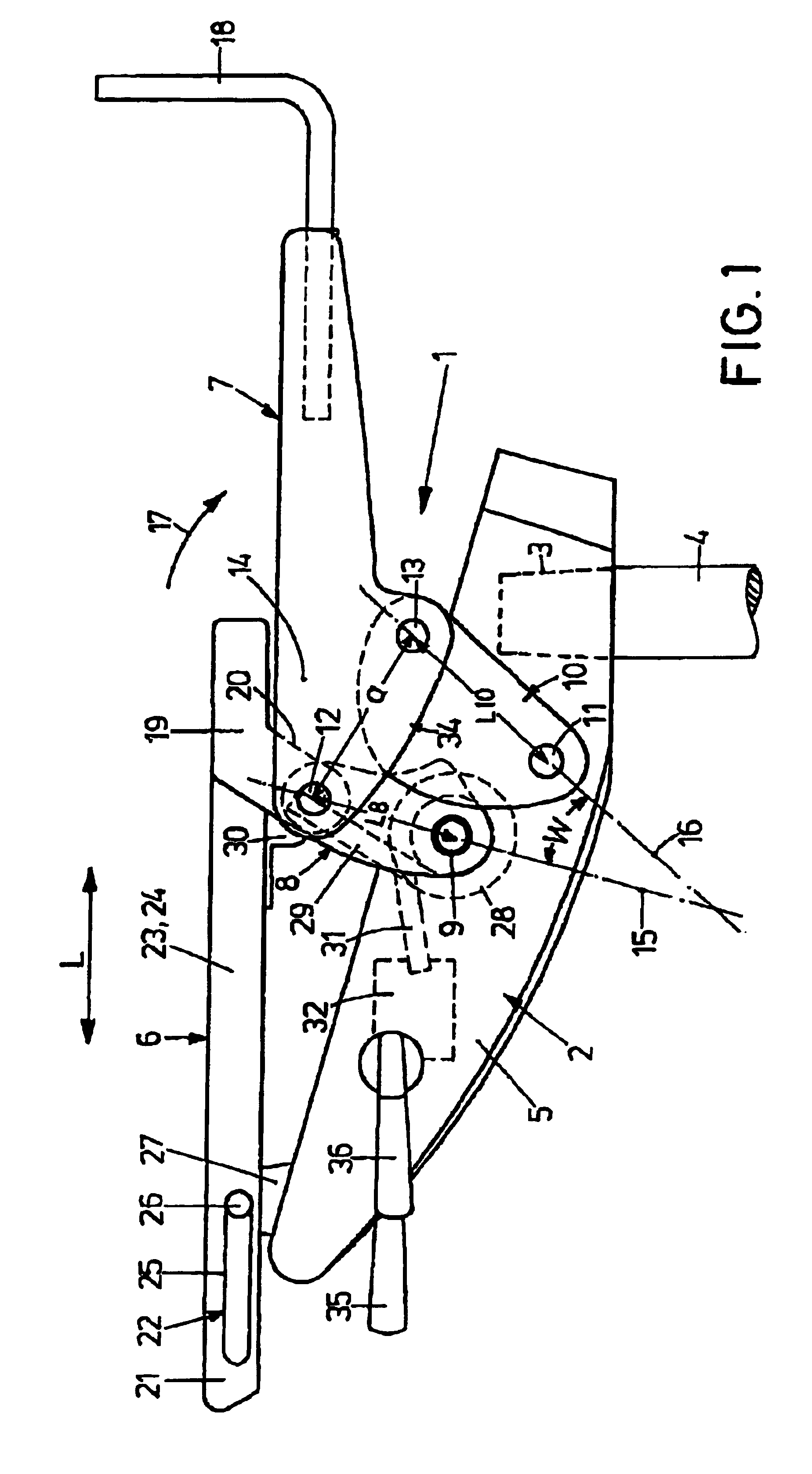
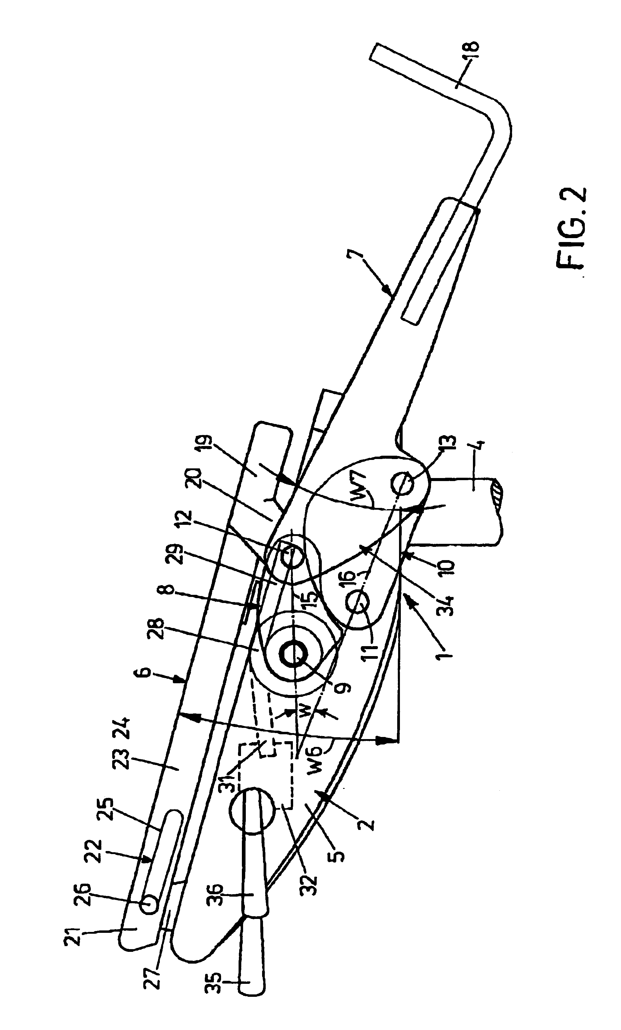
[0023]The fundamental structure of the synchronizing mechanism, which is denoted by 1 in its entirety, will be explained in conjunction with FIGS. 1 and 3. It comprises a base carrier 2 that is placed on the upper end of a chair column 4 by means of a cone receptacle 3. Various constructional elements of the synchronizing mechanism 1 are outside and above the lateral cheeks 5 that run parallel to the longitudinal direction L of the chair. The core pieces thereof are a substantially frame-type seat carrier 6 and a backrest carrier 7 which is forked seen in a plan view. Mounted on the seat carrier 6 is the seat (not shown) with an upholstered seat panel. By way of an elbowed cross arm 18, the backrest carrier 7 holds a backrest (not shown) which is vertically adjustable in today's office chairs.

[0024]In terms of kinematics, the entire synchronizing mechanism 1 is designed in mirror symmetry to the longitudinal center plane M as seen in particular in FIG. 3. In this regard, the ensuing...


PUM


Abstract

A synchronizing mechanism for correlated seat/backrest motion of an office chair is provided with a base carrier to be placed on a chair column; a seat carrier, which is pivotable about a transverse axis and, at its front end, articulated to the base carrier; and a backrest carrier, which is also pivotable about a transverse axis and articulated to the base carrier. It is coupled with the seat carrier such that a backward pivoting motion of the backrest induces a lowering motion of the rear end of the seat carrier. The joint between the base carrier and the seat carrier is a turning and sliding joint so that the lowering motion of the seat carrier is combined with a horizontal sliding motion.

Description

BACKGROUND OF THE INVENTION[0001]1. Field of the Invention[0002]The invention relates to a synchronizing mechanism for correlated seat / backrest motion of an office chair, comprising a base carrier to be placed on a chair column; a seat carrier, which is pivotable about a transverse axis and, at its front end, articulated to the base carrier; a backrest carrier, which is also pivotable about a transverse axis and articulated to the base carrier and which is coupled with the seat carrier such that a backward pivoting motion of the backrest induces a lowering motion of the rear end of the seat carrier; the backrest carrier being pivotably mounted on the base carrier by a cam arrangement that defines a four-bar chain; the cam arrangement being comprised of front and rear cams that are articulated to the base carrier and of the backrest carrier itself as a coupling of the four-bar chain; and the seat carrier, by its rear end, being articulated to the backrest carrier.[0003]2. Background ...

Claims


Application Information

Patent Timeline
IPC IPC(8): A47C1/031A47C1/032
CPCA47C1/03255A47C1/03294A47C1/03272A47C1/03205A47C1/03274
Inventor BOCK, HERMANN
Owner BOCK 1
Why Eureka
Try Eureka