Lantern and fuel system

a fuel system and lantern technology, applied in the field of lanterns and fuel systems, to achieve the effects of low manufacturing cost, convenient and efficient manufacturing and marketing, and durable and reliable construction

Inactive Publication Date: 2005-05-03
DRAPER DIANA CELEVATORON +1
View PDF10 Cites 4 Cited by
  • Summary
  • Abstract
  • Description
  • Claims
  • Application Information

AI Technical Summary

Benefits of technology

[0030]It is another object of the present invention to provide a new and improved lantern and fuel system which may be easily and efficiently manufactured and marketed.
[0031]It is further an object of the present invention to provide a new and improved lantern and fuel system which is of durable and reliable constructions.
[0032]An even further object of the present invention is to provide a new and improved lantern and fuel system which is susceptible of a low cost of manufacture with regard to both materials and labor, and which accordingly is then susceptible of low prices of sale to the consuming public, thereby making such lantern and fuel system economically available to the buying public.
[0033]Even still another object of the present invention is to provide a lantern and fuel system for allowing a user to safely and conveniently use a liquid fuel to provide heat and light.

Problems solved by technology

While these devices fulfill their respective, particular objectives and requirements, the aforementioned patents do not describe a lantern and fuel system that allows allowing a user to safely and conveniently use a liquid fuel to provide heat and light.

Method used


Image

  • Lantern and fuel system
  • Lantern and fuel system
  • Lantern and fuel system

Examples


Embodiment Construction

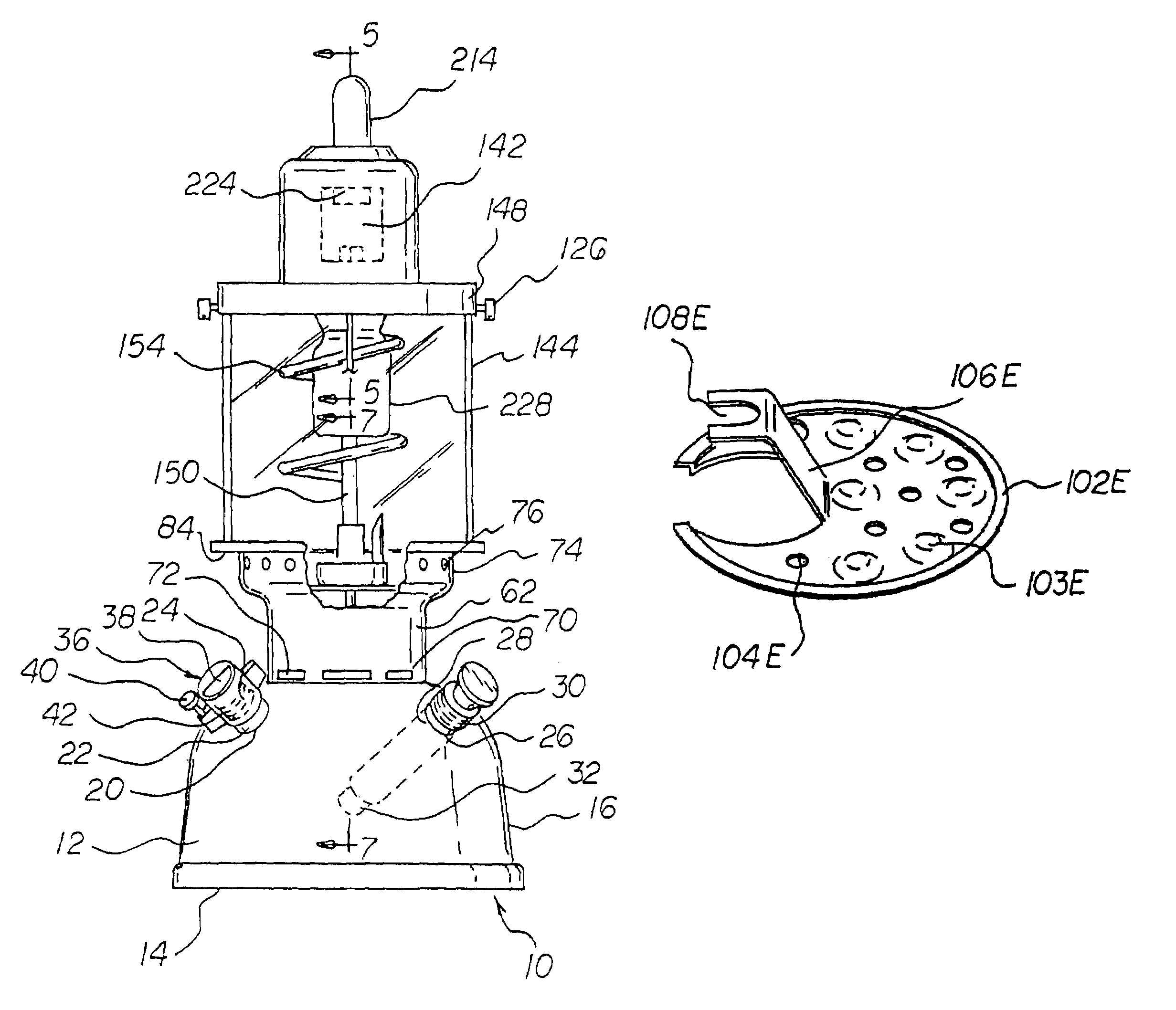
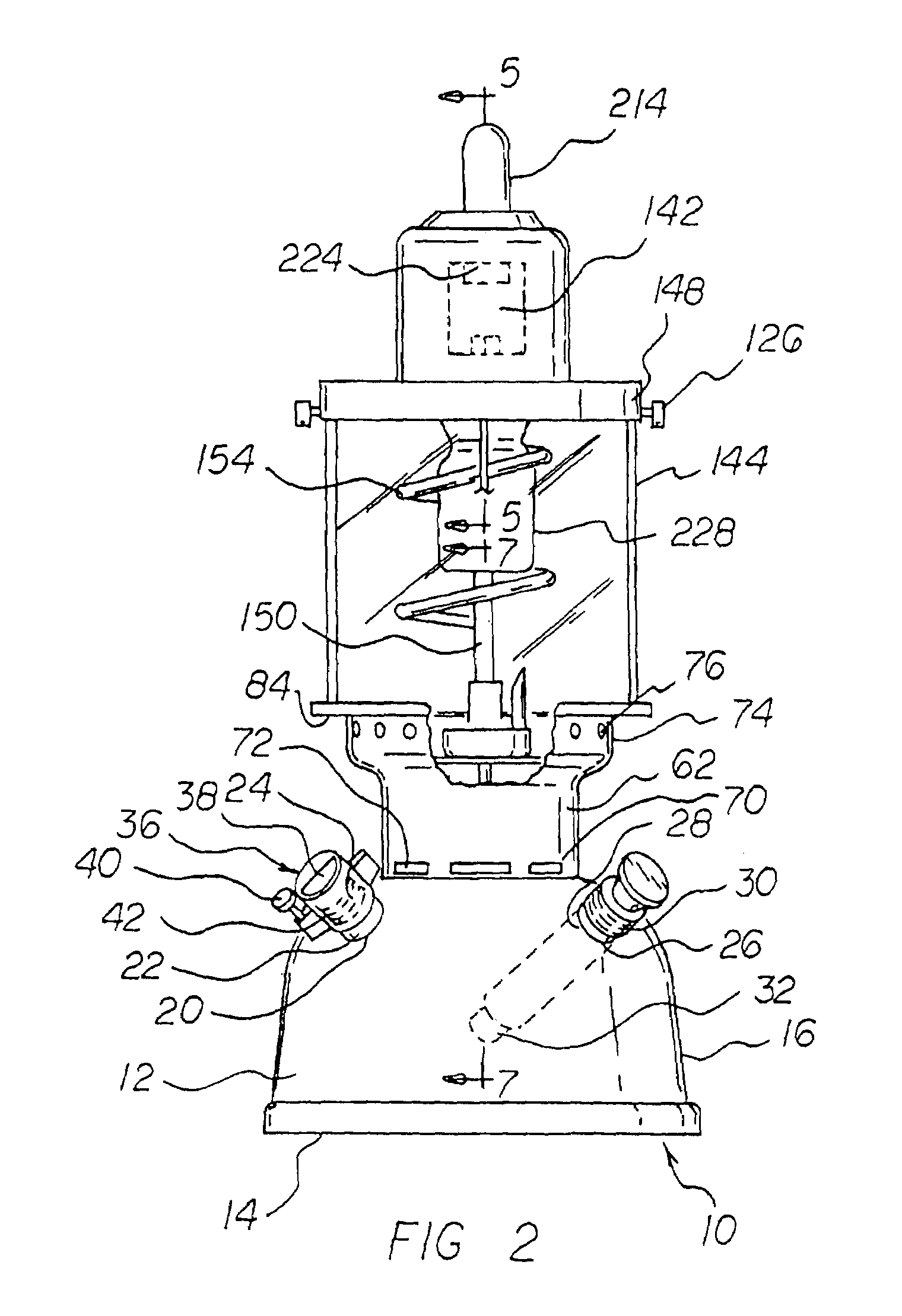
[0052]The present invention, the lantern and fuel system 10 is comprised of a plurality of components. Such components in their broadest context include a fuel tank, a pressure gauge subassembly, a pump subassembly, a lower skirt coupled to the tank, a lower skirt cap, an ignition bowl, a safety cover, a heat resistant glass chimney, an upper skirt, a lantern top cap, a plurality of connecting rods, a vaporizer and vaporizer cap, a quantity of steel wool, a J-shaped mixing tube, a mantel and a quantity of liquid methanol. Such components are individually configured and correlated with respect to each other so as to attain the desired objective.

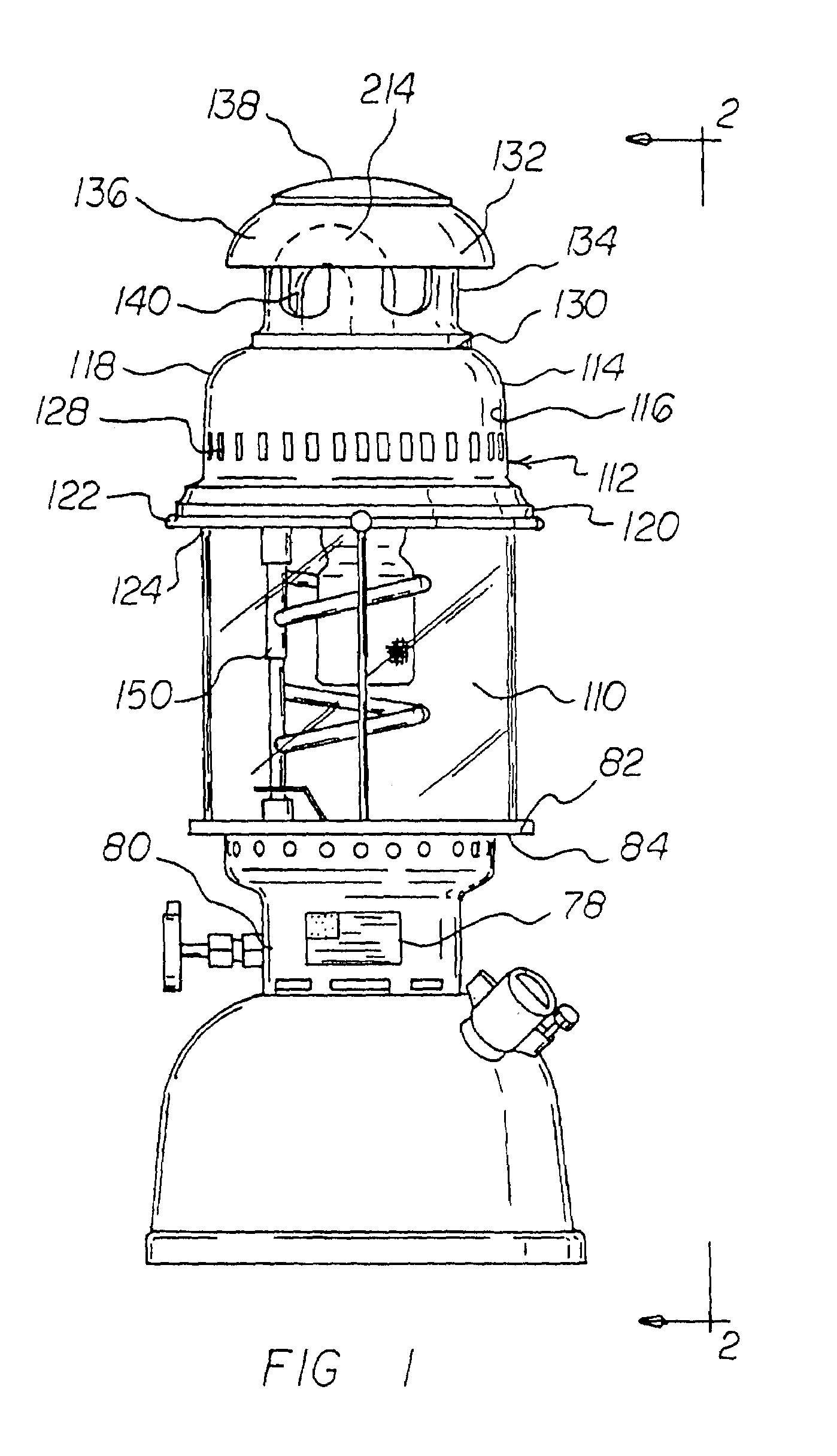
[0053]With reference now to the drawings, and in particular to FIG. 1 thereof, the preferred embodiment of the new and improved lantern and fuel system embodying the principles and concepts of the present invention and generally designated by the reference numeral 10 will be described.

[0054]First provided is a fuel tank 12. The fuel tank is fa...


PUM


Abstract

A lantern and fuel system with a safety cover, the safety cover having a round disc-like configuration, a plurality of radially spaced discontinuities of various sizes provided through the cover, the safety cover having a diameter sized to fit securely within the second diameter of a lower skirt, and a Z-shaped upward projection coupled to the cover with the projection having a notch at an uncoupled end.

Description

RELATED APPLICATIONS[0001]The present invention is a continuation-in-part application of parent application, U.S. patent application Ser. No. 10 / 389,896, to a lantern and fuel system and method filed on Mar. 17, 2003, and subsequently issued Feb. 10, 2004, as U.S. Pat. No. 6,688,877.BACKGROUND OF THE INVENTION[0002]1. Field of the Invention[0003]The present invention relates to a lantern and fuel system and more particularly pertains to allowing a user to safely and conveniently use a liquid fuel to provide heat and light.[0004]2. Description of the Prior Art[0005]The use of lantern and fuel systems of known designs and configurations is known in the prior art. More specifically, lantern and fuel systems of known designs and configurations previously devised and utilized for the purpose of providing heat and light are known to consist basically of familiar, expected, and obvious structural configurations, notwithstanding the myriad of designs encompassed by the crowded prior art whi...

Claims


Application Information

Patent Timeline
Patent Type & Authority Patents(United States)
IPC IPC(8): F23D11/46F23D11/30F23D11/36F23D11/44F23D11/24F21L19/00
CPCF21L19/00F23D11/46F23D11/443F23D11/30
Inventor DRAPER, DIANA CLIFTONDRAPER, GEORGE E.
Owner DRAPER DIANA CELEVATORON
Why Eureka
Try Eureka