Peritoneal dialysis catheter

Inactive Publication Date: 2005-05-10
MERIT MEDICAL SYST INC
View PDF11 Cites 20 Cited by
  • Summary
  • Abstract
  • Description
  • Claims
  • Application Information

AI Technical Summary

Benefits of technology

[0013]It is another object of the present invention to provide an improved peritoneal dialysis catheter which is suitable for continuous use, it presents an ideal, circular cross-sectional contour of portions of such catheter as pass through and reside in the abdominal wall of a recipient.
[0014]It is another object of the present invention to provide an improved peritoneal dialysis catheter which is suitable for continuous use, and which is of a design which minimizes the chances of conduit occlusion because of highly angular diversions of the conduits.
[0015]In satisfaction of these and related objects, the present invention provides an improved peritoneal dialysis catheter which, because of seemingly minor, but highly significant modifications from prior art designs, is unique in its manufacturerability and its capacity to serve as a continuous use peritoneal dialysis catheter without undue patient complications.
[0016]The peritoneal dialysis catheter design of the present invention, in the preferred embodiments, utilizes linearly mated conduits for that portion of the catheter which passes through the patient's abdominal wall (the trans-abdominal segment) and which cooperatively defines a substantially circular cross-sectional footprint. This feature pro

Problems solved by technology

However, the design of the ash catheter leaves certain characteristics of the ideal peritoneal dialysis catheter lacking.
However, Ash fails to provide an actual, workable design.
Ash's FIG. 4 depicts a proposed design for a continuous use peritoneal catheter, but one which simply cannot be made

Method used


Image

  • Peritoneal dialysis catheter
  • Peritoneal dialysis catheter
  • Peritoneal dialysis catheter

Examples


Embodiment Construction

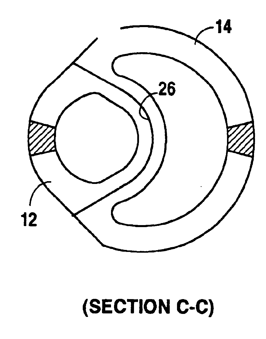
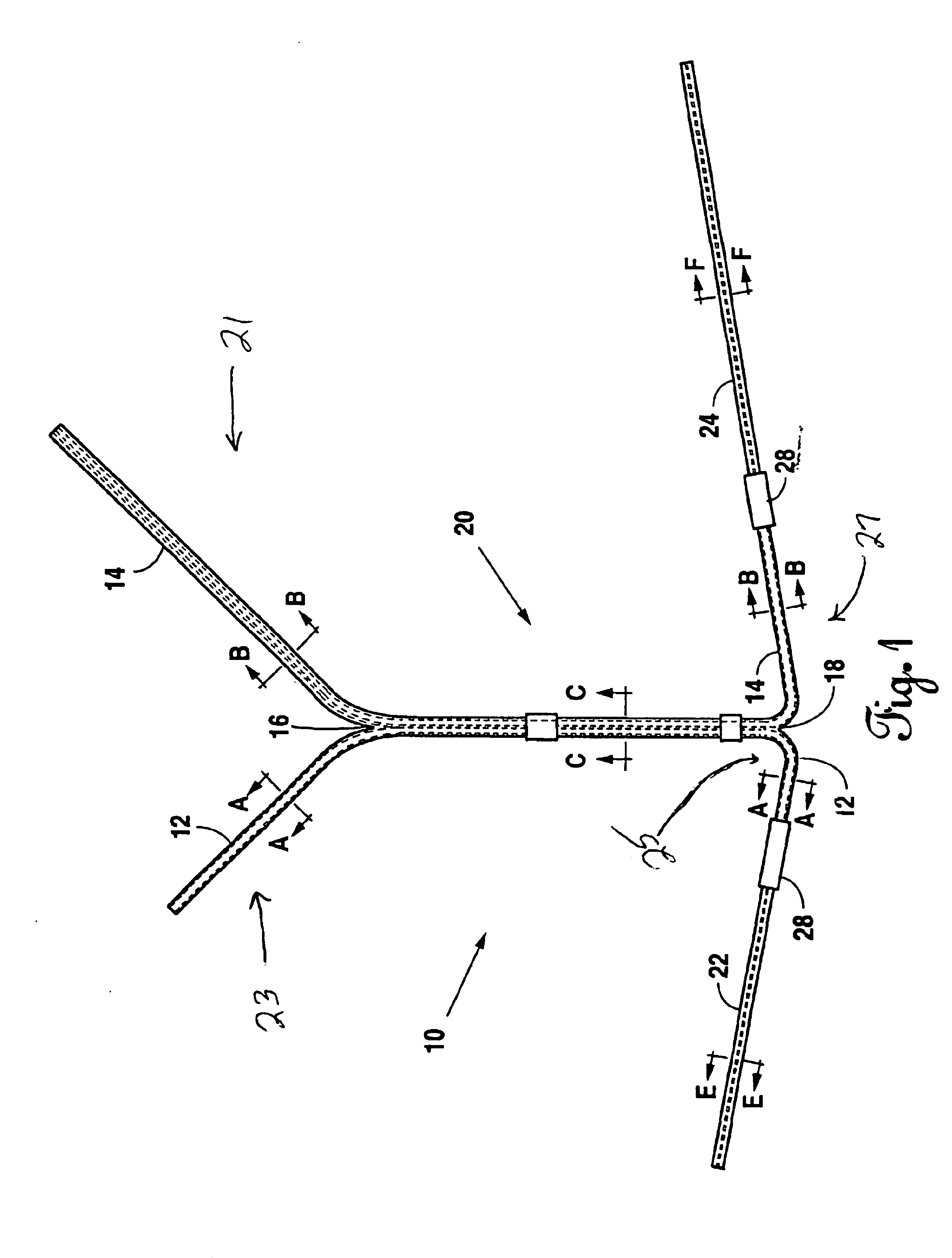
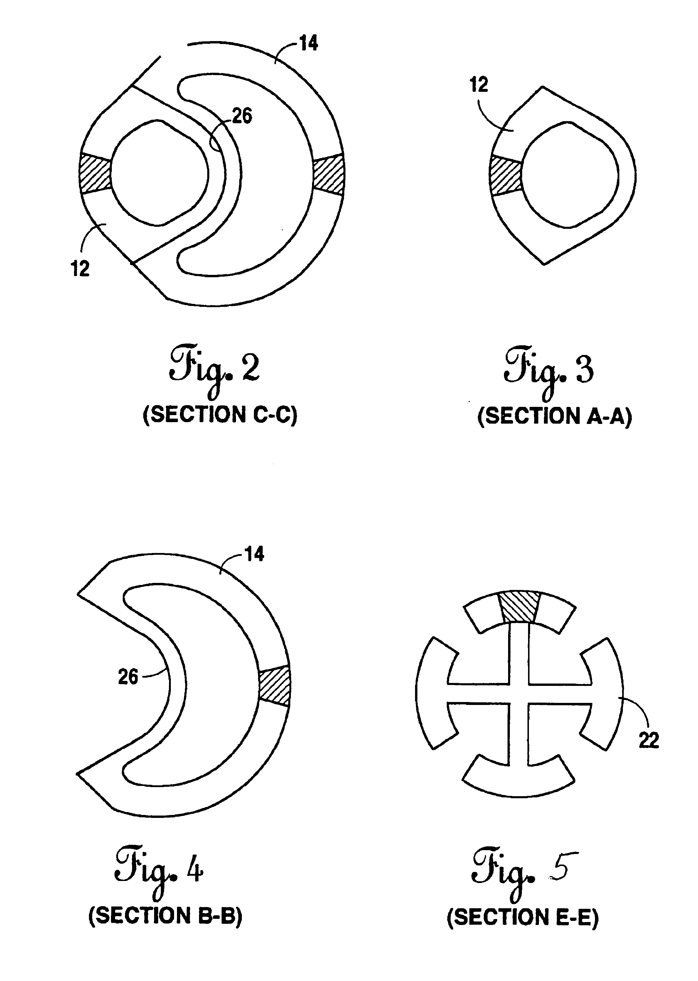
[0028]Referring to FIG. 1, a peritoneal catheter of the present invention is identified generally by the reference numeral 10. Peritoneal catheter 10 comprises, generally, an inflow conduit 12 and an outflow conduit 14.

[0029]In the embodiment shown in FIG. 1, at a proximal divergence point 16, proximal from which is proximal segments 21 and 23, inflow conduit 12 and outflow conduit 14 are not attached and extend to respective sources of fluids to be infused or receptacles for fluids expelled in the peritoneal dialysis process. In another embodiment, equally as good but not shown in the figures, inflow conduit 12 and outflow conduit 14 remain bonded proximal from divergence point 16. At a distal divergence point 18, distal from which is distal segments 25 and 27, inflow conduit 12 and outflow conduit 14 diverge as they respectively extend toward junctures with fluid transport branches 22 and 24.

[0030]In the shown embodiment FIG. 1, between proximal divergence point 16 and distal dive...


PUM


Abstract

A peritoneal dialysis catheter having an inflow conduit and an outflow conduit. Each conduits are linearly mated and contoured to cooperatively define a substantially circular cross sectional profile along a medial, trans-abdominal segment, but separating perhaps in radial fashion on either end of the medial, trans-abdominal segment, on a distal end to join fluted fluid transport branches and on proximal ends to join fittings for fluid delivery and collection external of the patient.

Description

CITATION TO PRIOR APPLICATION[0001]This is a continuation-in-part application with respect to U.S. application Ser. No. 09 / 811,340 filed Mar. 16, 2001 now U.S. Pat. No. 6,659,134, from which priority is claimed pursuant to 35 U.S.C. 120.BACKGROUND OF THE INVENTION[0002]1. Field of the Invention[0003]The present invention relates to medical catheters and to peritoneal dialysis catheters in particular.[0004]2. Background Information[0005]The foldable peritoneal dialysis catheter as disclosed in U.S. Pat. No. 5,322,519 (“the Ash catheter”) represented a substantial advance in peritoneal catheter design and technology. However, the design of the ash catheter leaves certain characteristics of the ideal peritoneal dialysis catheter lacking.[0006]The only feasible embodiments of the Ash catheter invention are those designed for inflow or outflow, but not both. Ash does teach the basic concept of a peritoneal dialysis catheter for continuous use (Column 4, lines 54 et seq.), in other words,...

Claims


Application Information

Patent Timeline
IPC IPC(8): A61M1/28
CPCA61M1/285
Inventor NAVIS, JOHN A.
Owner MERIT MEDICAL SYST INC
Why Eureka
Try Eureka