Combustion-powered nail gun

a nail gun and combustion technology, applied in the direction of nailing tools, manufacturing tools, stapling tools, etc., can solve the problems of operator fatigue, one shot cycle requires a prolonged period, etc., and achieve the effect of reducing physical fatigue of workers, enhancing nail driving efficiency, and quick piston return

Inactive Publication Date: 2005-05-10
KOKI HLDG CO LTD
View PDF11 Cites 51 Cited by
  • Summary
  • Abstract
  • Description
  • Claims
  • Application Information

AI Technical Summary

Benefits of technology

[0014]It is therefore, an object of the present invention to provide a combustion-powered nail gun capable of providing a rapid piston returning speed toward its upper dead center thereby enhancing nail driving efficiency and reducing physical fatigue of a worker.

Problems solved by technology

Consequently, one shot cycle requires a prolonged period, and an operator may be fatigued from such driving work.
This is particularly disadvantageous in case of a repeating shot type nail gun in which a trigger switch 112 is maintained in its ON position while successively driving a plurality of nails at different locations of the workpiece W by repeatedly pushing and releasing the push lever 121 toward and away from the workpiece W.

Method used


Image

  • Combustion-powered nail gun
  • Combustion-powered nail gun
  • Combustion-powered nail gun

Examples


Embodiment Construction

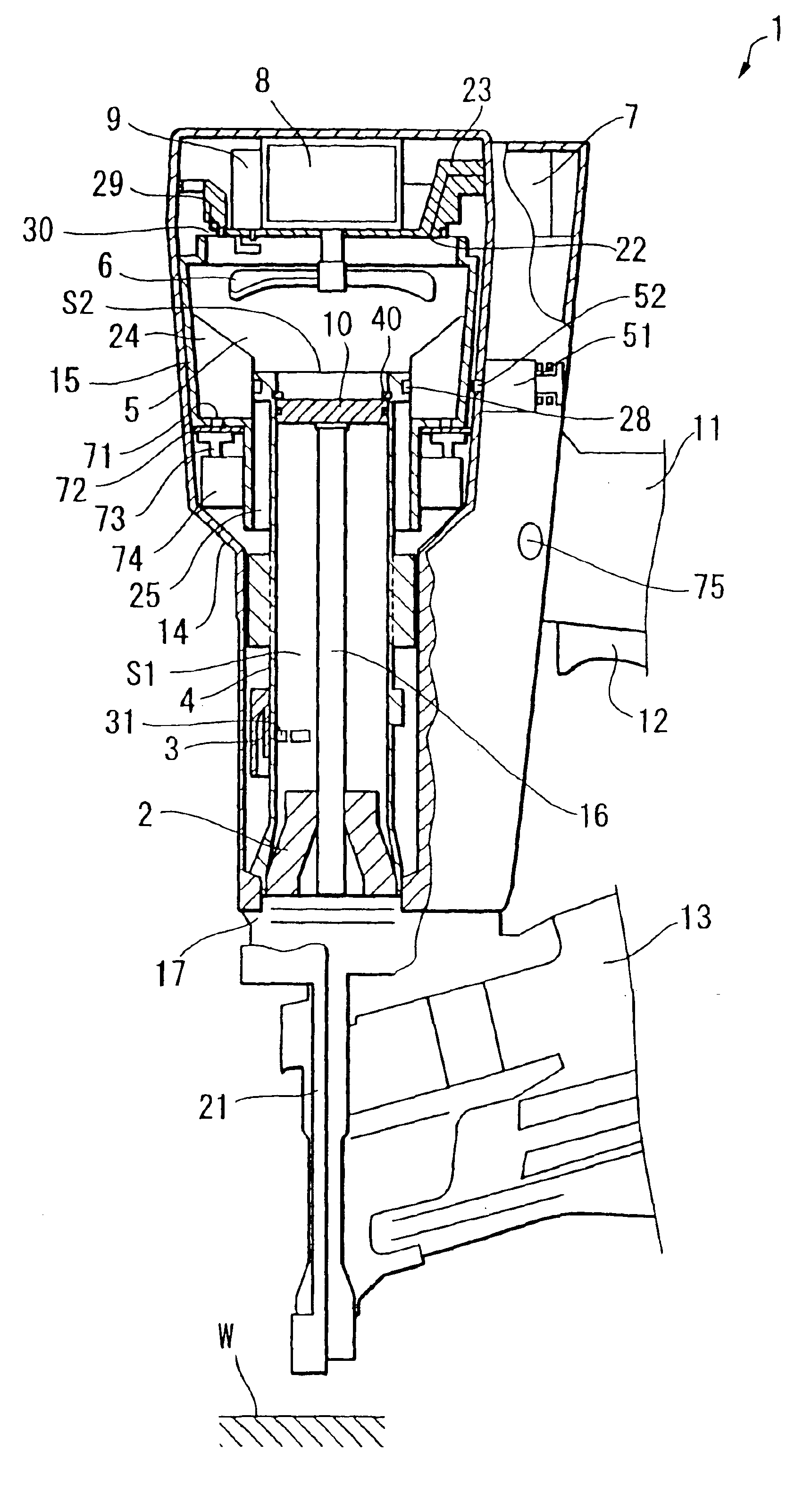
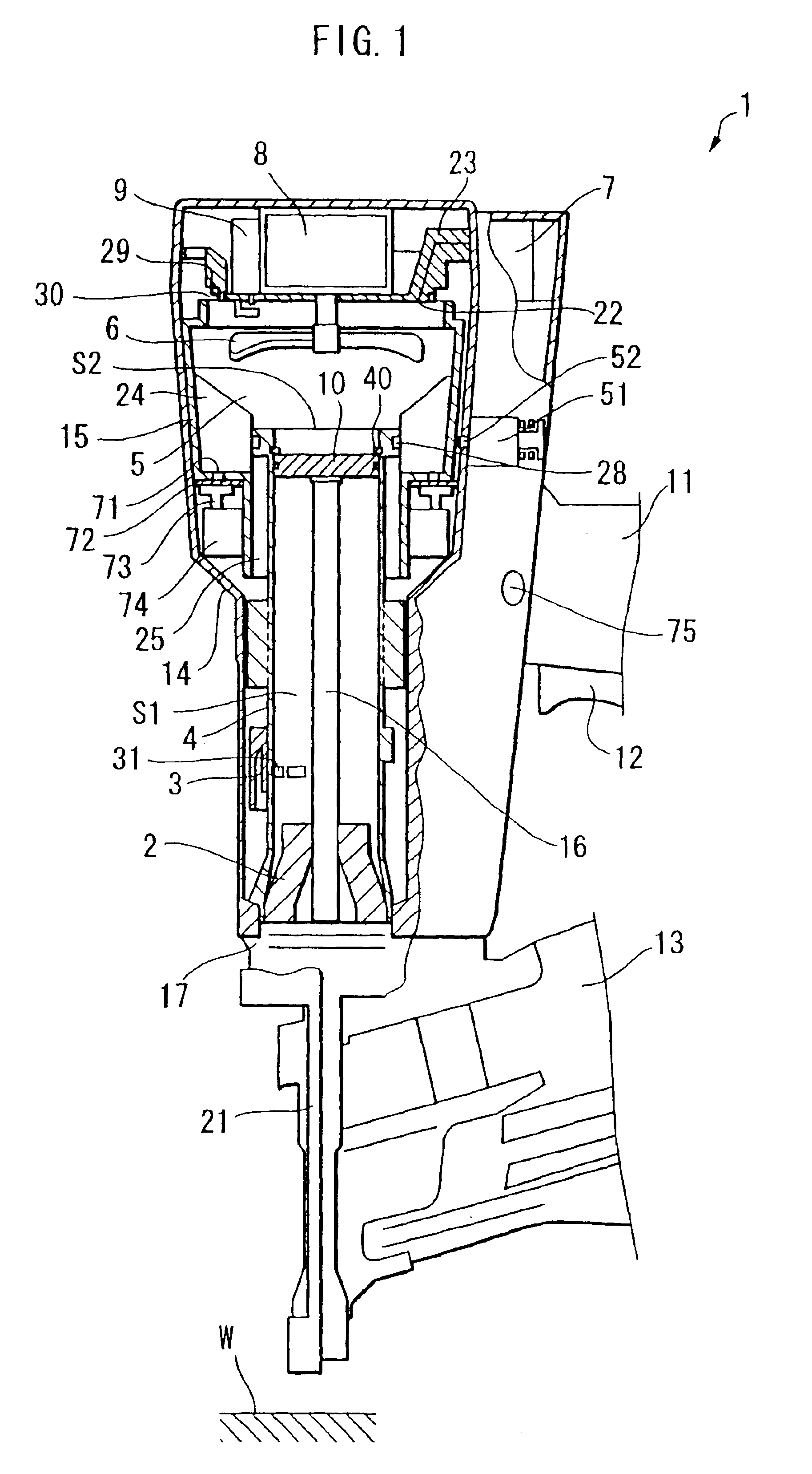
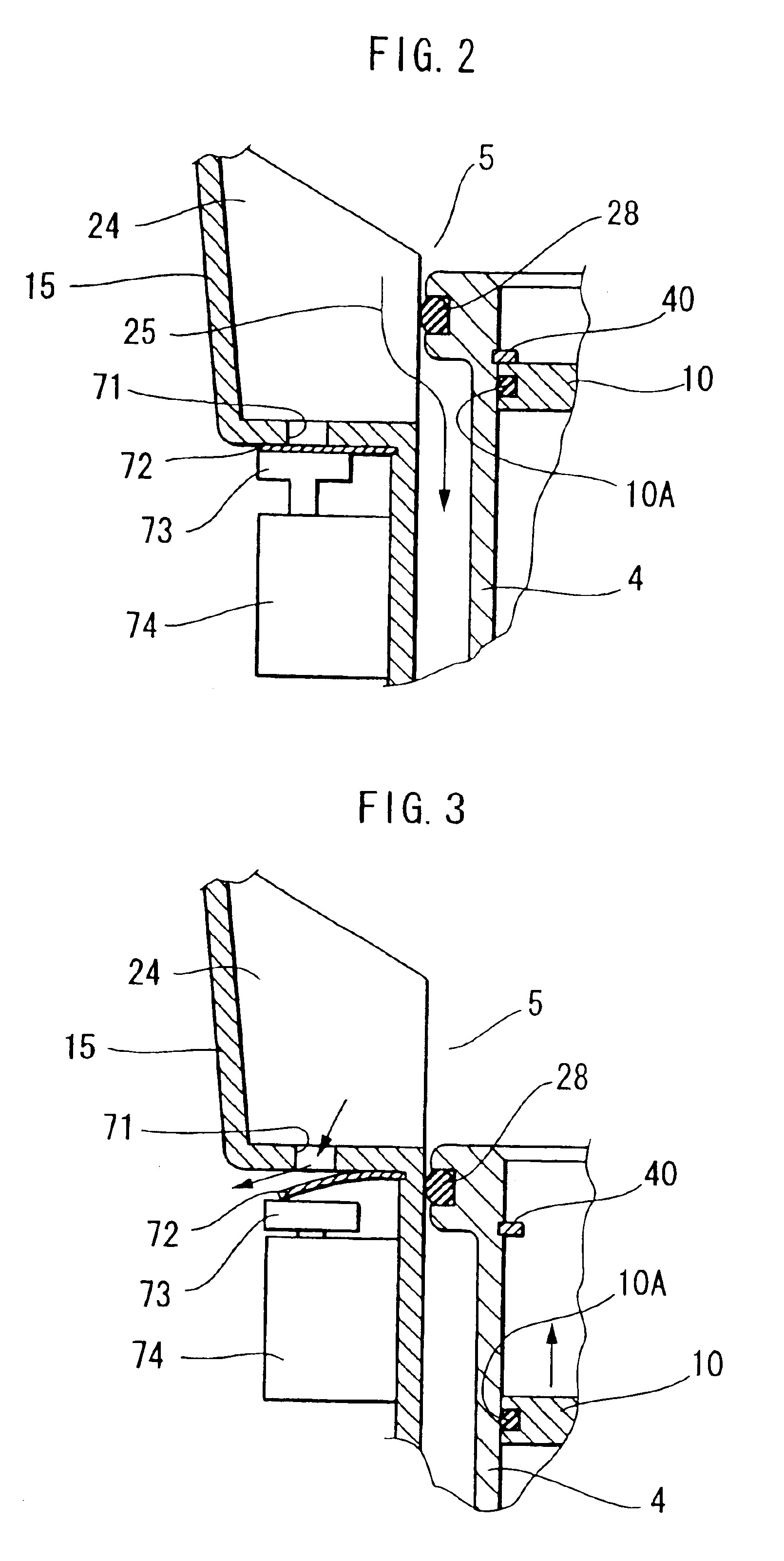
[0025]A combustion-powered nail guns according to one embodiment of the present invention will be described with reference to FIGS. 1 through 6.

[0026]A structure of a combustion powered nail gun 1 is almost the same as that of the conventional nail gun 100 shown in FIG. 8, The nail gun 1 includes a housing 14, a head cover 23, a combustion chamber frame 15, ribs 24, a cylinder 4, a piston 10, a driver blade 16, a handle 11, a trigger switch 12, a magazine 13, a tail cover 17, a push lever 21, a fan 6, a motor 8, a spark plug 9, and fuel canister 7 those similar to those of the conventional nail gun 100 shown in FIG. 8. The combustion chamber frame 15, the head cover 23, and the piston 10 together define a combustion chamber 5. Further, the piston 10 divides the cylinder 4 into a lower chamber S1 and an upper chamber S2 inclusive of the combustion chamber 5. The combustion chamber frame 15 is connected to the push lever 21 through a connection rod (not shown) for providing interlocki...


PUM

PropertyMeasurementUnit
movementaaaaaaaaaa
pressureaaaaaaaaaa
drive forceaaaaaaaaaa

Abstract

A combustion-powered nail gun including an arrangement for promoting a piston returning motion to its upper dead center. A combustion chamber frame is movable toward and away from a head cover at which a spark plug is provided. When the combustion chamber frame is in close contact with the head cover, a combustion chamber is provided among the combustion chamber frame, the head cover, a part of a cylinder and a piston. After the piston reaches the lower dead center as a result of combustion, a thermal vacuum is provided in the combustion chamber for allowing the piston to move toward the upper dead center. The combustion chamber frame has a through-hole, and a valve is provided for normally closing the through-hole. A solenoid is provided to selectively open the valve for leaking an increased pressure in the combustion chamber through the through-hole during the return stroke of the piston.

Description

BACKGROUND OF THE INVENTION[0001]The present invention relates to a combustion-powered nail gun that generates drive force by igniting a fuel / air mixture to drive a fastener such as a nail into a work piece.[0002]U.S. Pat. No. 4,403,722, 4,483,280 (U.S. Re. Pat. No. 32,452), U.S. Pat. Nos. 4,483,473, and 4,483,474 disclose combustion-powered tool assemblies. FIG. 8 schematically shows configuration of a conventional combustion-powered nail gun 100 similar to that disclosed in these U.S. Patents. The nail gun 100 includes a housing 114 to which a handle 111, a tail cover 117, a push lever 121, and a magazine 113 are disposed.[0003]The housing 114 accommodates therein a head cover 123, a combustion chamber frame 115, a cylinder 104, and a piston 110. The combustion chamber frame 115, the head cover 123, and the piston 110 together define a combustion chamber 105. Further, the piston 110 divides the internal space of the cylinder 104 and the combustion chamber frame 115 into upper cham...

Claims


Application Information

Patent Timeline
Patent Type & Authority Patents(United States)
IPC IPC(8): B25C1/08B25C1/00
CPCB25C1/08
Inventor OHMORI, YASUKI
Owner KOKI HLDG CO LTD
Why Eureka
Try Eureka