Center-located cutter teeth on shrouded turbine blades

a technology of cutter teeth and turbine blades, which is applied in the direction of machines/engines, mechanical equipment, liquid fuel engines, etc., can solve the problems of life-limiting locations, and achieve the effect of extending the creep life and minimizing stress

Inactive Publication Date: 2005-05-10
GENERAL ELECTRIC CO
View PDF20 Cites 29 Cited by
  • Summary
  • Abstract
  • Description
  • Claims
  • Application Information

AI Technical Summary

Benefits of technology

[0007]By locating the cutter tooth as described above, stresses are minimized in the tip shroud fillet. The location is approximately in line with the center of gravity of the tip shroud but this is not necessarily a requirement. The reduced stress extends creep life of the fillet which is frequently the life-limiting location of the part.

Problems solved by technology

The reduced stress extends creep life of the fillet which is frequently the life-limiting location of the part.

Method used


Image

  • Center-located cutter teeth on shrouded turbine blades
  • Center-located cutter teeth on shrouded turbine blades
  • Center-located cutter teeth on shrouded turbine blades

Examples


Embodiment Construction

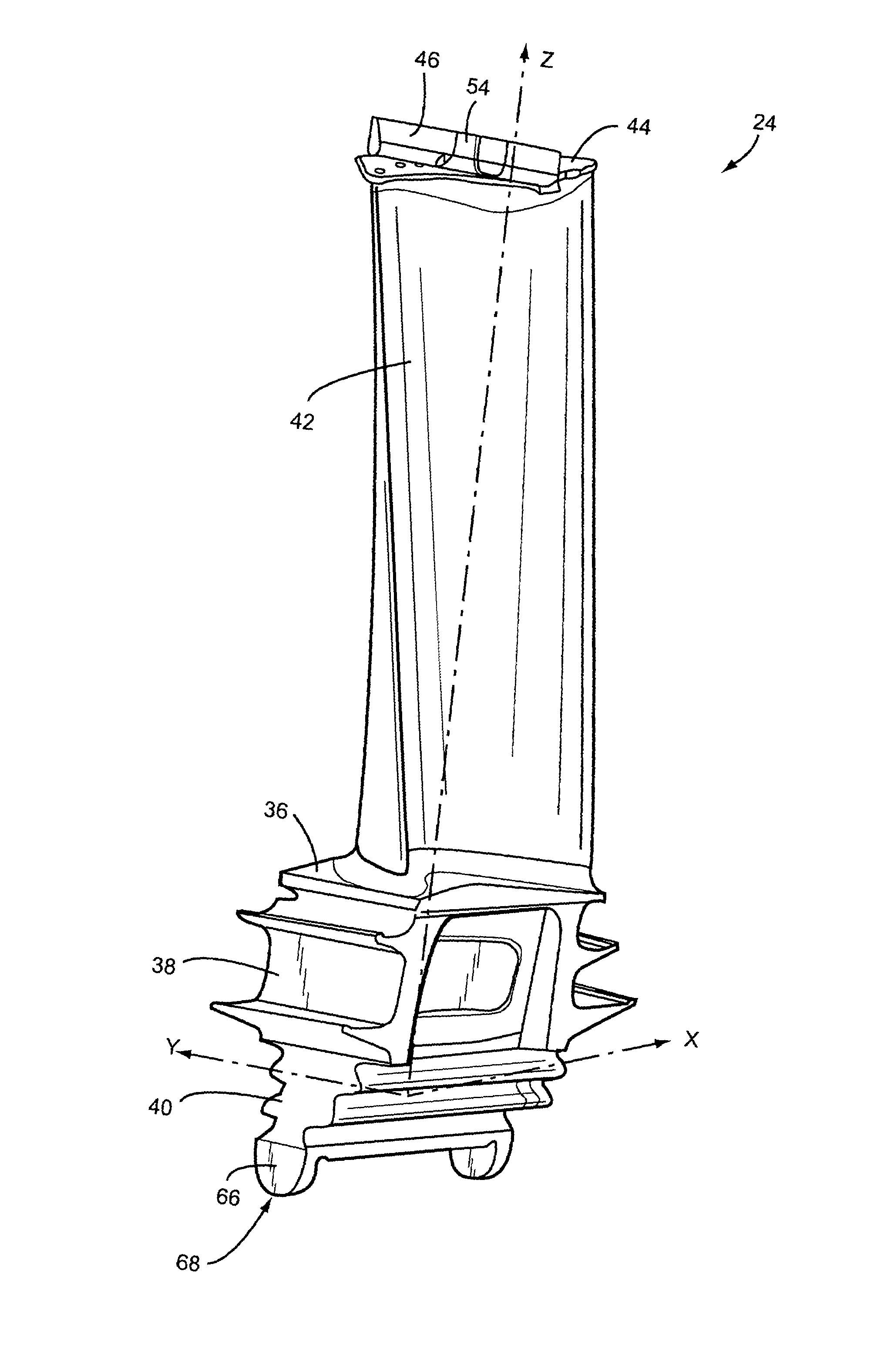
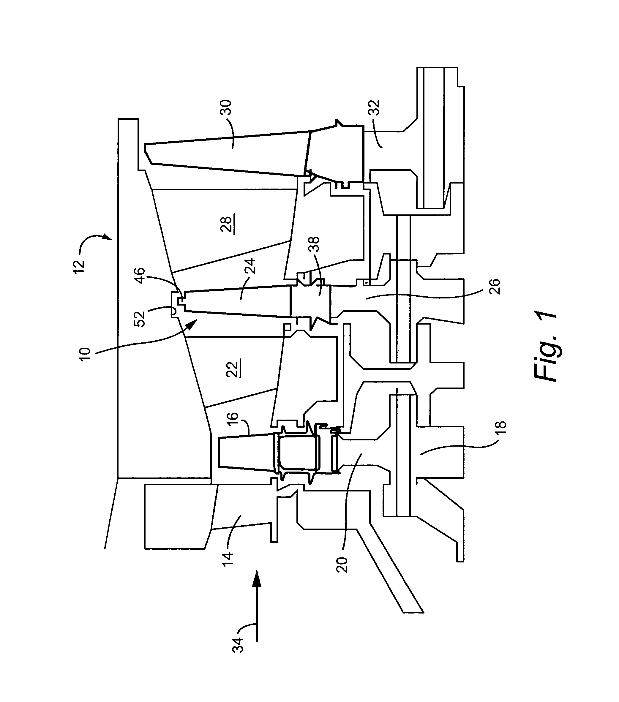
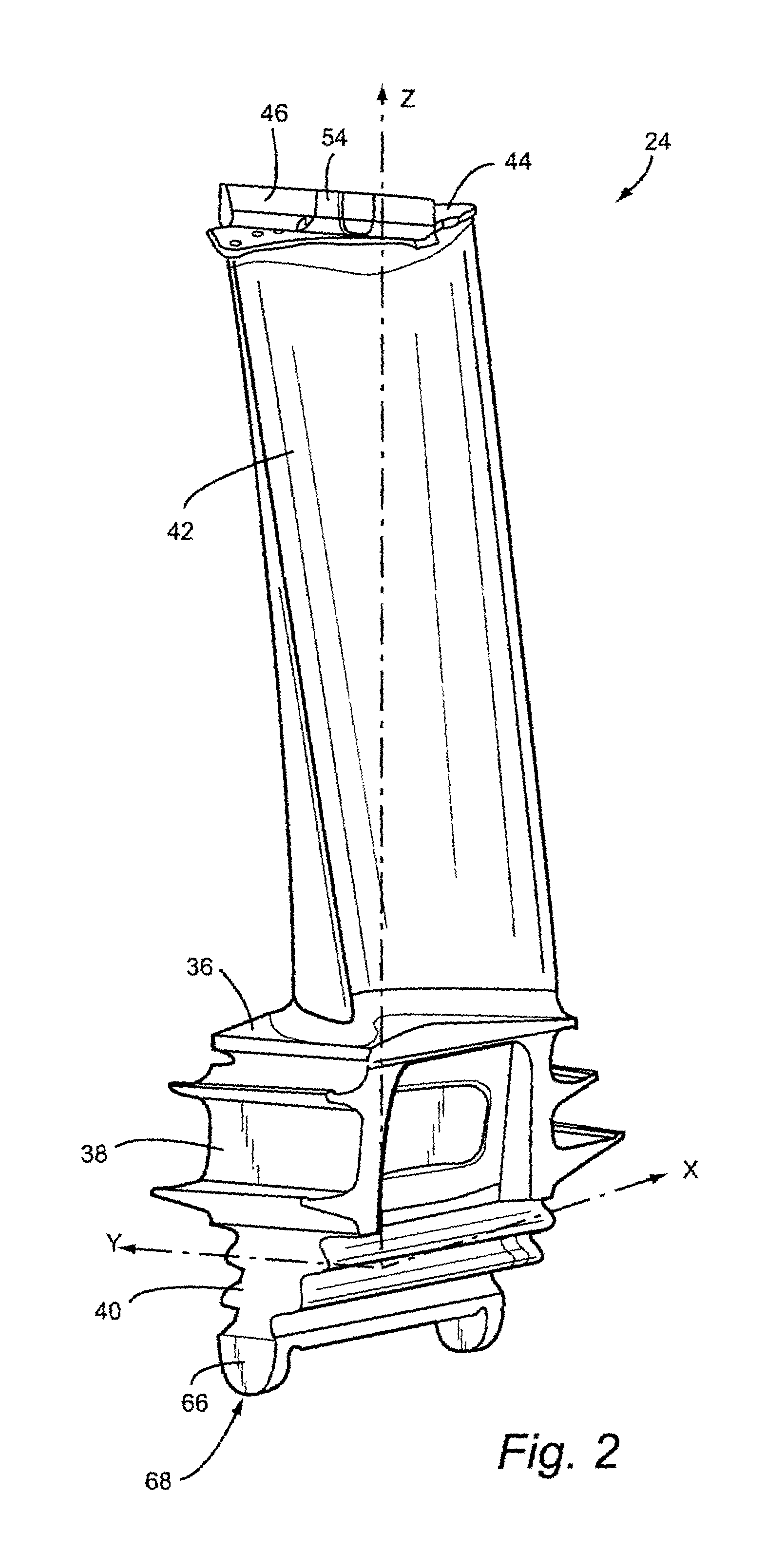
[0022]Referring now to the drawings, particularly to FIG. 1, there is illustrated a hot gas path, generally designated 10, of a three-stage gas turbine 12. The first stage comprises a plurality of circumferentially spaced nozzles 14 and buckets 16. The nozzles are circumferentially spaced one from the other and fixed about the longitudinal center axis of the rotor. The first stage buckets 16 are mounted on the turbine rotor 18 via a rotor wheel 20. The second stage of the turbine 12 includes a plurality of circumferentially spaced nozzles 22 and a plurality of circumferentially spaced buckets 24, also mounted on the rotor 18, via rotor wheel 26. The third stage includes a plurality of circumferentially spaced nozzles 28 and buckets 30 mounted on rotor 18 via wheel 32. It will be appreciated that the nozzles and buckets lie directly in the hot gas path 10 of the turbine, the direction of flow of the hot gas through the hot gas path 10 indicated by the arrow 34.

[0023]This invention re...


PUM


Abstract

A turbine bucket includes an airfoil having a tip shroud, a shank and an entry dovetail; a tip shroud seal projecting radially outwardly from the tip shroud and extending continuously between end edges of the tip shroud in a direction of rotation of the airfoil about a turbine axis; a cutter tooth carried by the tip shroud seal for enlarging a groove in an opposing fixed shroud, the cutter tooth having a center point located with reference to X, Y and Z axes, where the X-axis extends axially in an exhaust flow direction; the Y-axis extends in a direction of rotation of the turbine bucket; and the Z-axis extends radially through the intersection of the X and Y axes; wherein the center point is located about ½ inch along the Y-axis from the X=0 position, and wherein the Z-axis is located 0.517 inches from an outside edge of a seal pin extending along said entry dovetail, as measured in a direction normal to the shank of the bucket.

Description

BACKGROUND OF THE INVENTION[0001]The present invention relates to turbine buckets having airfoil tip shrouds and, particularly, to a shroud for a stage 2 bucket having a tip seal extending between opposite ends of the shroud, with a cutter tooth located along said tip seal, substantially centered between the opposite ends of the shroud in the direction of rotation of the bucket.[0002]Airfoils on turbine buckets are frequently provided with tip shrouds. The shroud prevents failure of the airfoil in high cycle fatigue due to vibratory stresses. A tip shroud seal typically projects radially outwardly from the outermost surface of the shroud, and extends circumferentially between opposite ends of the shroud in the direction of rotation of the turbine rotor. The tip shroud seal conventionally extends radially into a groove formed in a stationary shroud opposing the rotating tip shroud. In some designs, the stationary shroud has a honeycomb pathway. Rather than providing a zero tolerance ...

Claims


Application Information

Patent Timeline
Patent Type & Authority Patents(United States)
IPC IPC(8): F01D5/14F01D5/20F01D11/08F02C7/28
CPCF01D5/141F01D5/225F05D2240/30F05B2240/33
Inventor TOMBERG, STEVEN ERIC
Owner GENERAL ELECTRIC CO
Why Eureka
Try Eureka