Unlock instant, AI-driven research and patent intelligence for your innovation.

Heater with glow plug/flame monitor

a glow plug and monitor technology, applied in the direction of combustion process, fuel additives, combustion ignition, etc., can solve the problems of extreme smoke emissions and inability to monitor the flame continuously

Inactive Publication Date: 2005-05-10
WEBASTO THERMOSYST INT
View PDF7 Cites 0 Cited by
  • Summary
  • Abstract
  • Description
  • Claims
  • Application Information

AI Technical Summary

Benefits of technology

"The present invention provides a motor vehicle with a heater that can continuously monitor flame during the starting phase of the heater, even during the glow plug ramp time interval. This is achieved by measuring the resistance value of the glow plug / flame monitor and comparing it to a threshold value. The invention can be used during the glow plug ramp time interval, when the electrical power supplied to the glow plug is reduced or increased. The invention can provide a quick and accurate response to flame blow-off and can be used in conjunction with a time-dependent function to determine the threshold value for flame-out detection. The invention can also use gradient evaluation of the resistance value to consider the effect of the electrical power supplied to the glow plug / flame monitor during monitoring."

Problems solved by technology

Existing methods of flame monitoring by means of a glow plug / flame monitor have the disadvantage that during the starting phase, i.e., during glow operation of the glow plug, continuous monitoring of the flame is not possible.
This problem arises especially for small heaters up to 5 kW heat output.
Extreme smoke emissions can occur to some extent by flame blow-off during the currently unmonitored starting phase.

Method used


Image

  • Heater with glow plug/flame monitor
  • Heater with glow plug/flame monitor

Examples


Embodiment Construction

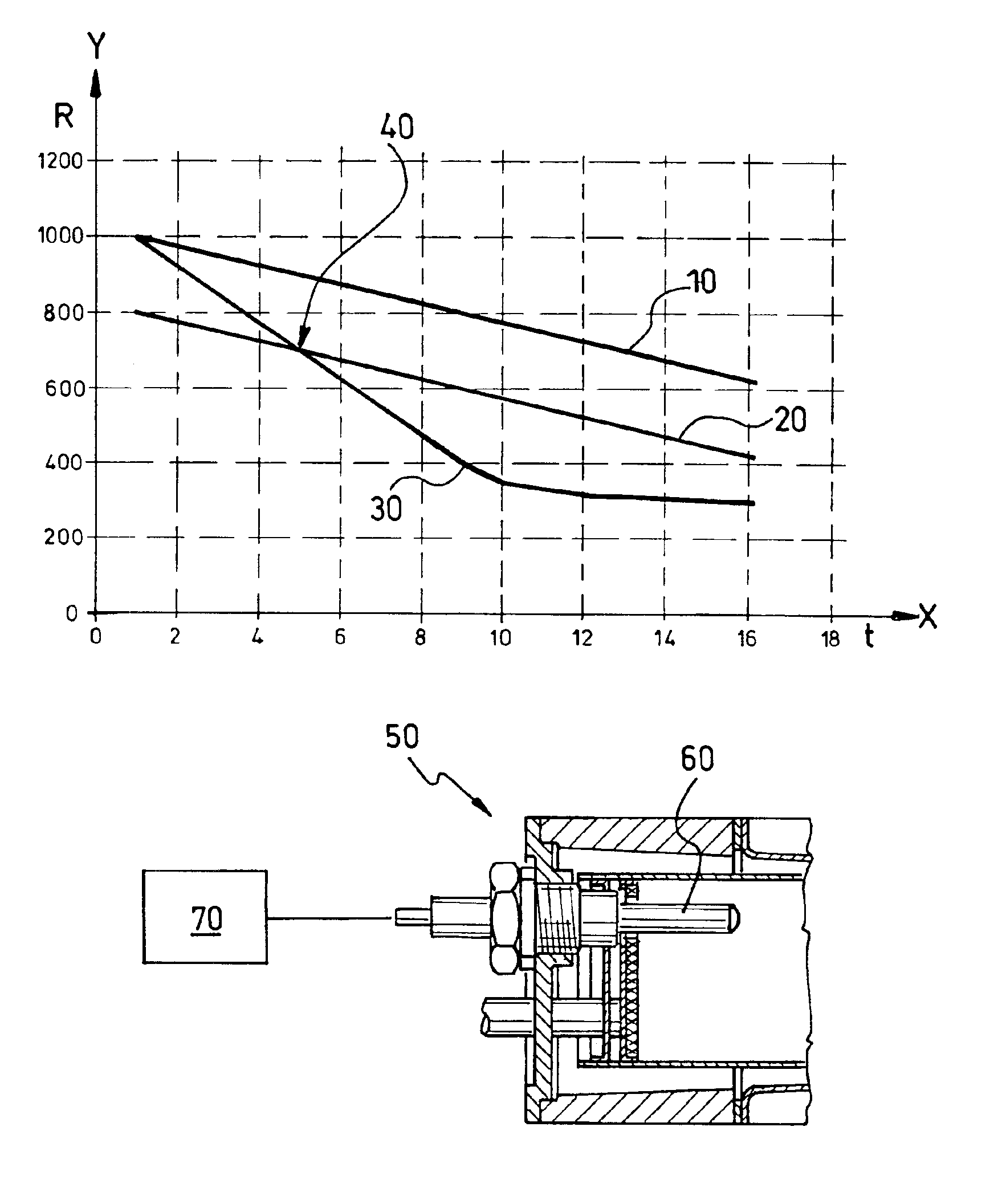
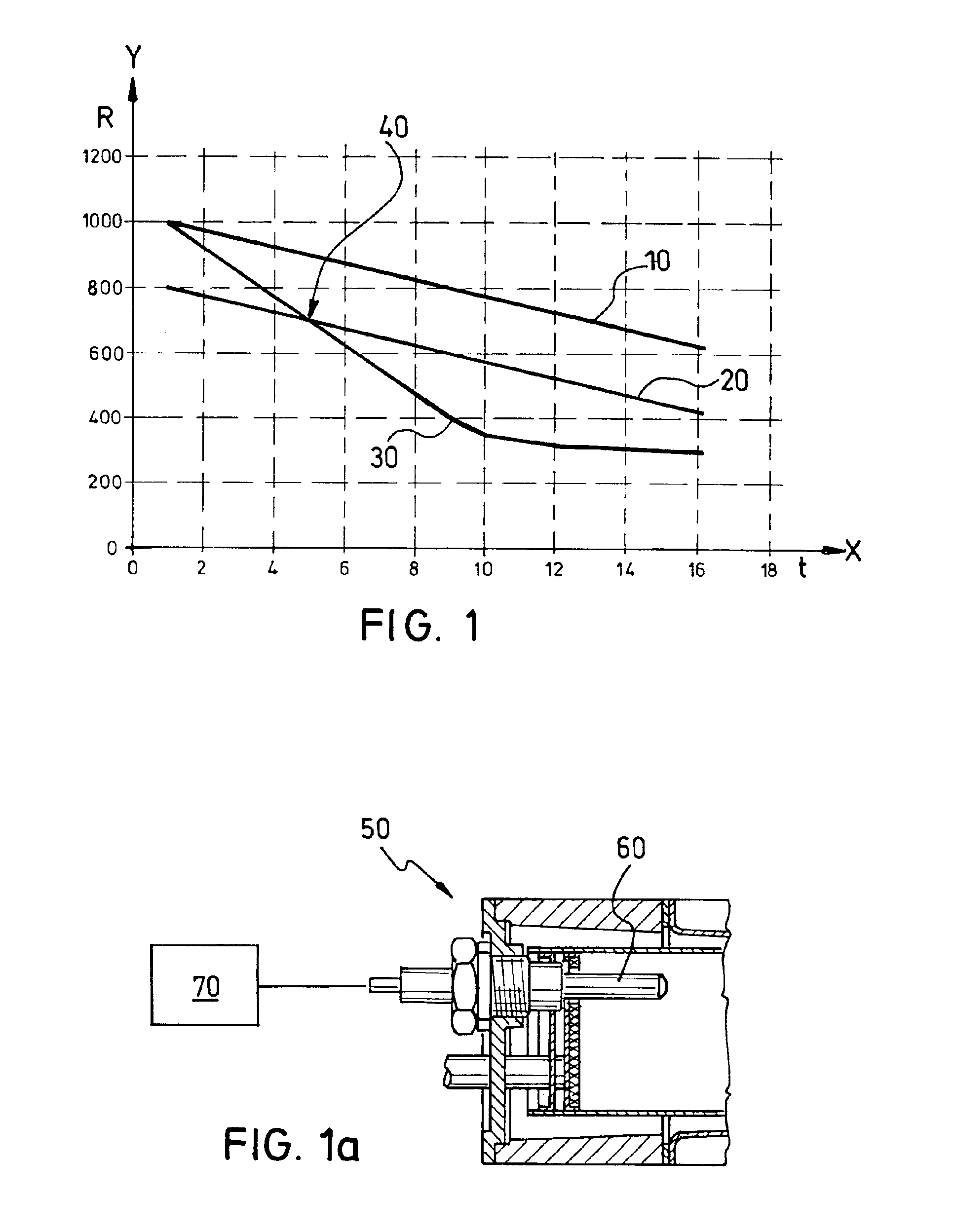
[0024]In FIG. 1, on the X-axis, a characteristic is plotted over time in the unit seconds (sec). The Y-axis illustrates resistance values in the unit milliohm (mΩ).

[0025]The line or curve 10 of FIG. 1 shows the characteristic of the resistance value of a glow plug 60, illustrated in FIG. 1a, on the burner of a heater 50 during a glow plug ramp time interval (i.e., during the glow process) for a flame-on situation. The line or curve 20 shows the characteristic of a threshold value which changes over time and which is determined based on a function RGS=f(t) xx. Finally, the line or curve 30 shows the characteristic of the resistance value on the glow plug in the presence of a flame-out situation.

[0026]The function RGS is determined proceeding from a resistance value Rstart of the glow plug at the start of the glow plug ramp time interval of 1000 mΩ. Then a linear characteristic between the resistance value Rstart of the glow plug and the resistance value Rend of the glow plug at the e...


PUM


Abstract

A heater in which, during the glow plug ramp time interval, the amount of energy supplied per unit of time to the glow plug / flame monitor can be successively changed, and a control unit which is operationally coupled to the glow plug / flame monitor. To enable continuous flame monitoring during the starting phase of the heater with the control unit, the resistance value of the glow plug / flame monitor is determined during the glow plug ramp time interval and compared to a threshold value RGS, and when the threshold value RGS is not reached, a flame-out signal is generated.

Description

BACKGROUND OF THE INVENTION[0001]1. Field of the Invention[0002]The invention relates to a heater with a glow plug / flame monitor in which, during glow plug ramp time intervals, the amount of energy supplied per unit of time can be successively changed, especially reduced, and with a control unit which is operationally coupled to the glow plug / flame monitor. Furthermore, the invention relates to a motor vehicle which is provided with such a heating device.[0003]2. Description of Related Art[0004]German Patent DE 198 22 140 C1 discloses a process for flame monitoring in a motor vehicle heater in which the resistance value of a glow plug is evaluated, during glow pauses in which there is no power supply voltage on the glow plug, by a control unit for detecting a flame in a combustion chamber. Monitoring takes place by checking whether the glow coils of the glow plug assume a predetermined resistance value within a given time interval.[0005]Published German Patent Application DE 199 03 ...

Claims


Application Information

Patent Timeline
Patent Type & Authority Patents(United States)
IPC IPC(8): F23N5/14
CPCF23N5/143F23N2029/22F23N2029/06F23N2027/42F23N2227/42F23N2229/06F23N2229/22
Inventor BACKER, CHRISTIANHOGLMAIER, WERNERWOLF, FELIX
Owner WEBASTO THERMOSYST INT