Method of forming carbon fibers

a technology of carbon fibers and carbon fibers, which is applied in the direction of carbon fiber chemical treatment, textiles and paper, carbonsing rags, etc., can solve the problems of limited progress in controlling the diameter of these materials

Inactive Publication Date: 2005-05-10
PENN STATE RES FOUND
View PDF6 Cites 53 Cited by
  • Summary
  • Abstract
  • Description
  • Claims
  • Application Information

AI Technical Summary

Benefits of technology

[0009]An advantage of the present invention is a method of manufacturing carbon fiber / tubes.
[0010]Additional advantages and other features of the present invention will be set forth in the description which follows and in part will be apparent to those having ordinary skill in the art upon examination of the following or may be learned from the practice of the present invention. The advantages of the present invention may be realized and obtained as particularly pointed out in the appended claims.
[0011]According to the present invention, the foregoing and other advantages are achieved in part by a method of a manufacturing a carbon article, e.g. a carbon fiber or nanotube. The method comprises preparing a metal catalyst system having one or more diluents; and pyrolyzing the metal catalyst system to form the carbon fiber / tube. The diluents can be non-metal ligands, i.e. metal-free organic compounds such as chelators.
[0012]Embodiments include preparing a metal catalyst system by adding a non-metal diluent to a metal catalyst, e.g. adding a phthalocyanine or derivative thereof to a nickel phthalocyanine metalorganic to form the metal catalyst system, and pyrolyzing the metal catalyst system from about 100° C. to about 1000° C.
[0013]Another aspect of the present invention includes a method of controlling the diameter of a carbon fiber / tube. The method comprises preparing a metal catalyst system by adding a diluent to a metal catalyst; and pyrolyzing the metal catalyst system to form a carbon fiber / tube with a diameter corresponding to the diluted metal catalyst.
[0014]Additional advantages of the present invention will become readily apparent to those skilled in this art from the following detailed description wherein embodiments of the present invention are described simply by way of illustrated of the best mode contemplated for carrying out the present invention. As will be realized, the present invention is capable of other and different embodiments, and its several details are capable of modifications in various obvious respects, all without departing from the present invention. Accordingly, the drawings and description are to be regarded as illustrative in nature, and not as restrictive.

Problems solved by technology

Despite efforts in preparing carbon fiber / tubes, limited progress has been realized in controlling the diameters of these materials, particularly controlling the diameter of carbon nanotubes.

Method used


Image

  • Method of forming carbon fibers
  • Method of forming carbon fibers

Examples


example

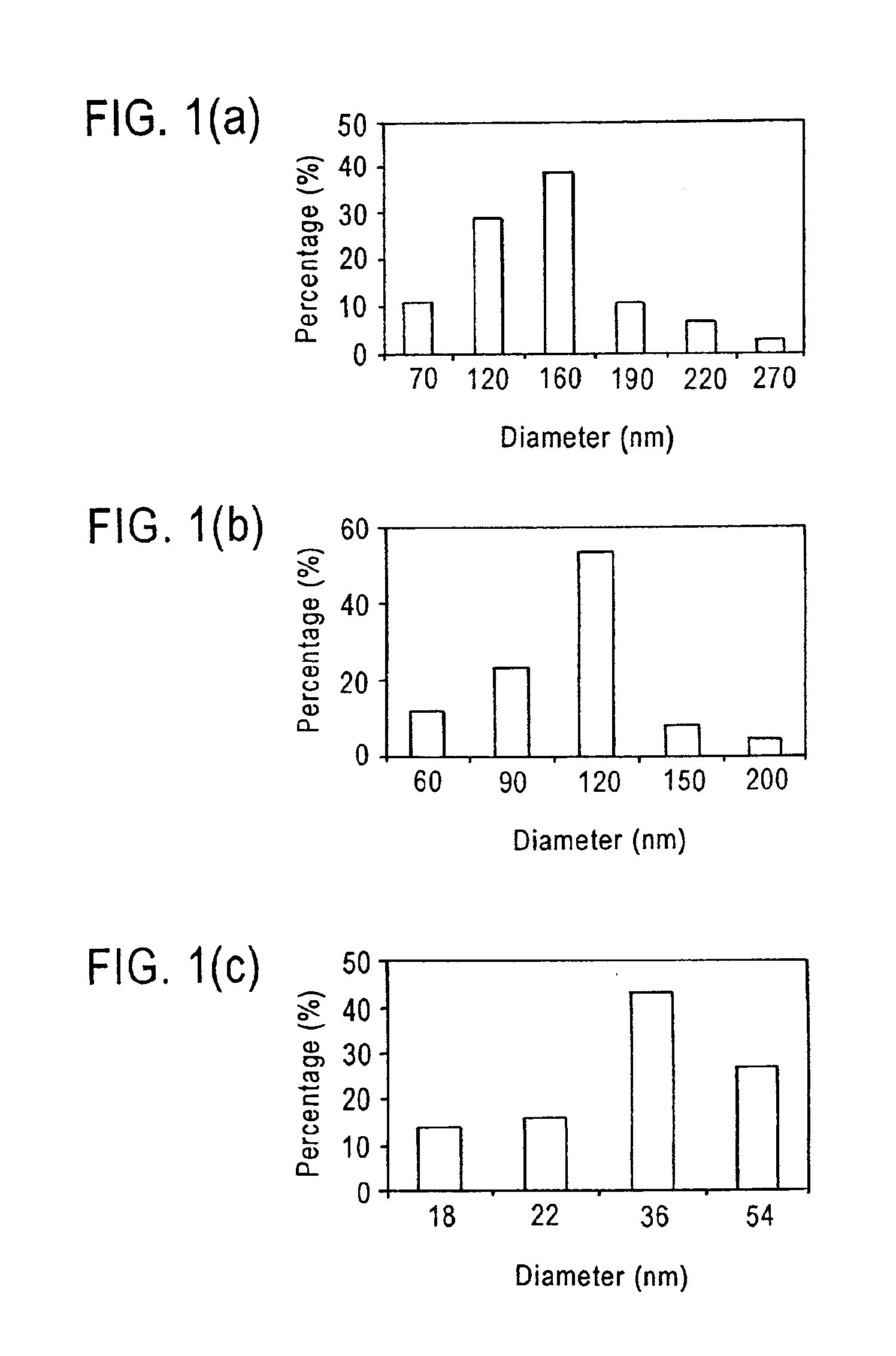
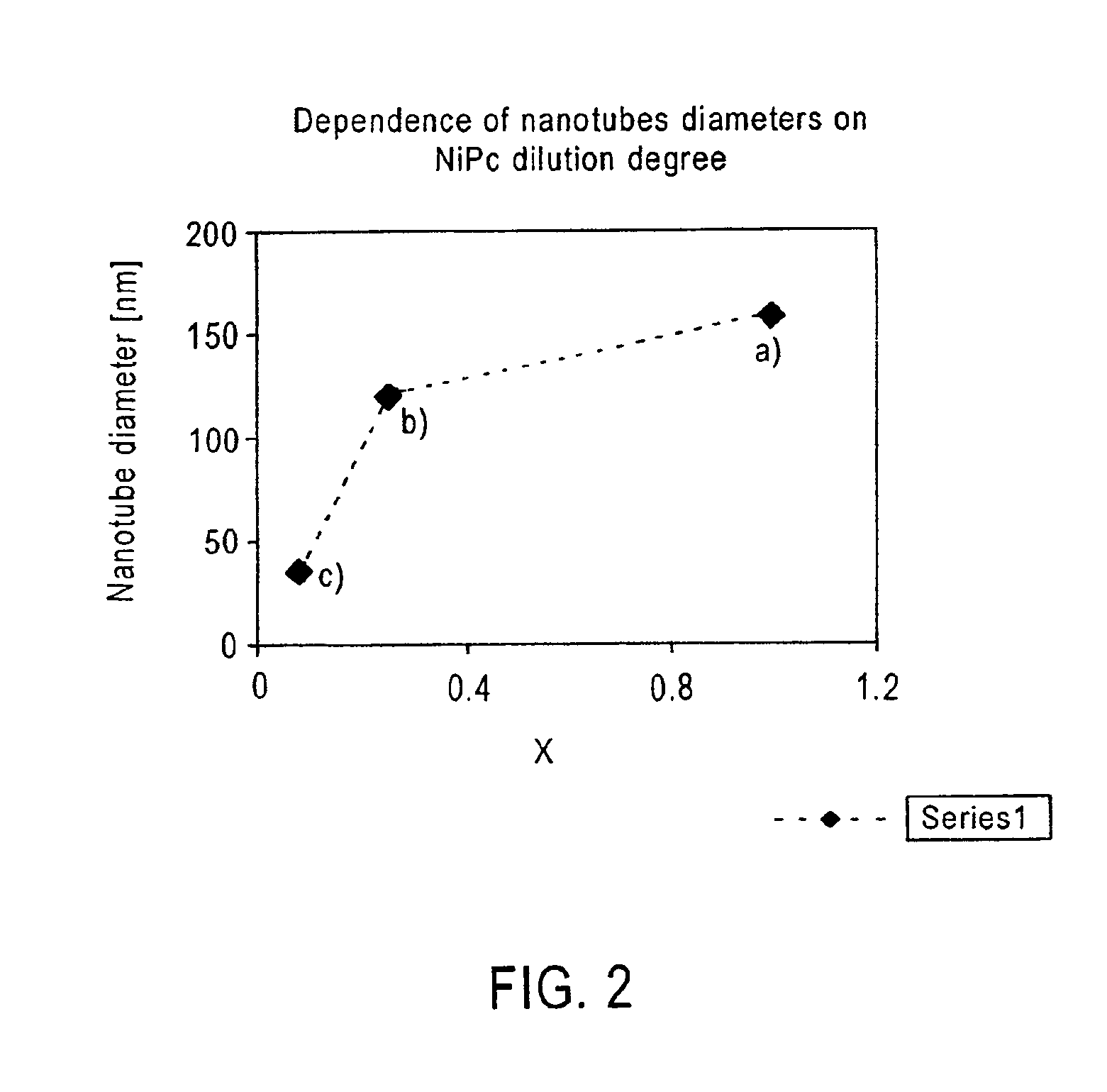
[0026]An example of forming a carbon nanotube with various sized diameters was undertaken. In this example, NiPc was prepared with metal-free Pc (H2Pc) and used as both a catalyst and a carbon source at the same time. As a further example of metal diluents, the present invention also contemplates catalyst systems that are diluted by the addition of metal diluents. For example, composition having (M1Pc)x(M2Pc)1-x where M1 and M2 are different metals are also contemplated.

[0027]In this example, phthalocyanines were purified by twice subliming the sample at about 480° C. under vacuum. This produces predominately the beta form of MPc (where M is a metal), the more stable of its polymorphic forms. Diluted catalyst systems were prepared by subliming a predetermined mixture of NiPc with H2Pc powders in a desired proportion to yield (NiPc)x(H2Pc)1-x. Three different catalysts were prepared where x is 1, 0.25 and 0.08 by this method.

[0028]Carbon nanotubes were then formed by pyrolyzing the c...


PUM

PropertyMeasurementUnit
temperatureaaaaaaaaaa
lengthaaaaaaaaaa
diameteraaaaaaaaaa

Abstract

Carbon fiber/tubes are prepared by pyrolyzing a catalyst system that contains one or more diluents to facilitate control of the diameter of the formed carbon fiber/tube.

Description

RELATED APPLICATION[0001]The present application claims priority to U.S. Provisional Application Ser. No. 60 / 283,472 filed 12 Apr. 2001 and entitled “METHOD FOR CONTROLLING THE DIAMETER OF CARBON NANOTUBES”, the entire disclosure of which is hereby incorporated in its entirety herein by reference.FIELD OF THE INVENTION[0002]The present invention relates to a method for the production of elongated carbonaceous articles, such as carbon fibers and nanotubes. The present invention has particular applicability in manufacturing carbon nanotubes having variously sized diameters.BACKGROUND[0003]Carbon-based materials, in general, enjoy wide utility due to their unique physical and chemical properties. Recent attention has turned to the use of elongated carbon-based structures, such as carbon filaments, carbon tubes, and in particular nanosized carbon structures. It has been shown that these new structures impart high strength, low weight, stability, flexibility, good heat conductance, and a...

Claims


Application Information

Patent Timeline
Patent Type & Authority Patents(United States)
IPC IPC(8): D01F9/12
CPCD01F9/12
Inventor HARUTYUNYAN, AVETIKPRADHAN, BHABENDRA K.EKLUND, PETER C.
Owner PENN STATE RES FOUND
Why Eureka
Try Eureka