Lamination sheet and core lamination structure of a motor

a technology of lamination sheet and core, which is applied in the direction of dynamo-electric machines, electrical apparatus, magnetic circuit shapes/forms/construction, etc., can solve the problems of reducing productivity, complex fabrication process, and high cost of manufacturing time, and achieves the effect of simple fabrication

Inactive Publication Date: 2005-05-10
LG ELECTRONICS INC
View PDF13 Cites 5 Cited by
  • Summary
  • Abstract
  • Description
  • Claims
  • Application Information

AI Technical Summary

Benefits of technology

[0016]Therefore, an object of the present invention is to provide a method for core lamination in a motor and a lamination structure thereof by...

Problems solved by technology

However, according to the conventional art, the laminated body of the lamination sheets L is fixed and coupled by welding, and therefore the fabrication process is complex and the it costs much time to fabricate, whereby the productivity is lowered.
Also, the unit laminat...

Method used


Image

  • Lamination sheet and core lamination structure of a motor
  • Lamination sheet and core lamination structure of a motor
  • Lamination sheet and core lamination structure of a motor

Examples


first embodiment

[0036]Hereinafter, the motor core laminating method and the lamination structure thereof according to the present invention will be described as follows.

[0037]FIGS. 4 and 5 are showing an embodiment of a motor including the motor core lamination structure according to the present invention. As shown therein, the motor comprises: a stator (S) including an outer core 100 and an inner core 20 formed as a cylinder so as to be inserted into the outer core 100; a winding coil 30 coupled to inside of the outer core 100 or the inner core 20; and an armature 40 including a permanent magnet and inserted between the outer core 100 and the inner core 20 so as to be moved. The winding coil 30 is coupled into the outer core 100 in the accompanying figure.

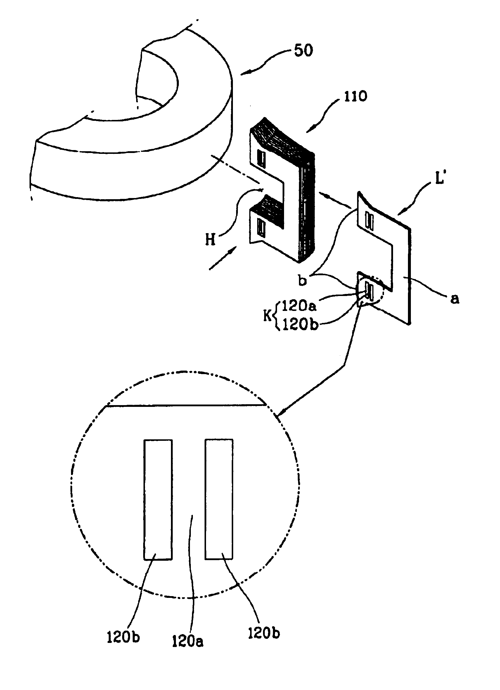
[0038]In addition, the outer core 100 included the stator S is formed such that a plurality of unit lamination cores 110, in which a plurality of lamination are laminated to be a predetermined thickness, are coupled to the bobbin 50 of ring shape...

second embodiment

[0051]FIGS. 9 and 10 are showing an embodiment of a motor including the motor core lamination structure according to the present invention. As shown therein, the motor comprises a stator S including an outer core 200 and an inner core 20 formed as a cylinder so as to be inserted into the outer core 200, a winding coil 30 coupled to inside of the outer core 200, and an armature 40 including a permanent magnet 41 and inserted between the outer core 200 and the inner core 20 so as to be moved.

[0052]In addition, the outer core 200 constructing the stator S comprises a plurality of unit lamination cores 210, in which a plurality of lamination sheets L″ formed by thin plates of predetermined shape are laminated so as to have a predetermined thickness, coupling portions 213, which are protruded so as to be engaged with each other and therefore the lamination sheets L″ can be moved relatively, are formed on the respective lamination sheets L″ constructing the unit lamination core 210. There...


PUM


Abstract

A core lamination structure in a motor is constructed such that a plurality of lamination sheets of a predetermined shape are laminated to form a laminated body, that is, a unit lamination core. The unit lamination core formed by the plurality of lamination sheets is fixedly coupled by a caulking portion or a coupling portion formed on the respective lamination sheet and connected with the adjacent lamination sheets to be in a row. In this way, a fabricating process of the unit lamination core is made to be easy and simple to reduce time for fabricating, and a curvature for a curved surface portion of the unit lamination core can be changed so that the present invention can be applied to various motors according to the capacity or the size of the motor.

Description

BACKGROUND OF THE INVENTION[0001]1. Field of the Invention[0002]The present invention relates to a method for core lamination in a motor and lamination structure thereof, and particularly, to a core laminating method and the lamination structure in the motor by which a curvature of a laminated body which is made by laminating a plurality of lamination sheets and coupled to a bobbin can be changed, and a structure and a fabrication can be made simply.[0003]2. Description of the Background Art[0004]Generally, a reciprocating motor is made by changing a magnetic flux of a general motor having a steric structure to be a plane shape, that is, a movable portion of plane shape is linearly moved on a plane according to changes of magnetic flux formed on a fixed portion on the plane.[0005]FIGS. 1 and 2 are showing an example of the reciprocating motor, and as shown therein, the reciprocating motor comprises: a stator S including an outer core 10 and an inner core 20 formed as a cylinder so a...

Claims


Application Information

Patent Timeline
IPC IPC(8): H02K1/14H02K15/02H02K1/18H02K33/16
CPCH02K1/145H02K15/022H02K2201/09
Inventor PARK, KYEONG BAE
Owner LG ELECTRONICS INC
Why Eureka
Try Eureka