Power-saving reading of magnetic memory devices

a magnetic memory device and power saving technology, applied in the field of memory devices, can solve the problem of significant current loss

Inactive Publication Date: 2005-05-10
SAMSUNG ELECTRONICS CO LTD
View PDF5 Cites 111 Cited by
  • Summary
  • Abstract
  • Description
  • Claims
  • Application Information

AI Technical Summary

Problems solved by technology

Again, the amount of current lost can be significant when taken in the aggregate.

Method used


Image

  • Power-saving reading of magnetic memory devices
  • Power-saving reading of magnetic memory devices
  • Power-saving reading of magnetic memory devices

Examples


Embodiment Construction

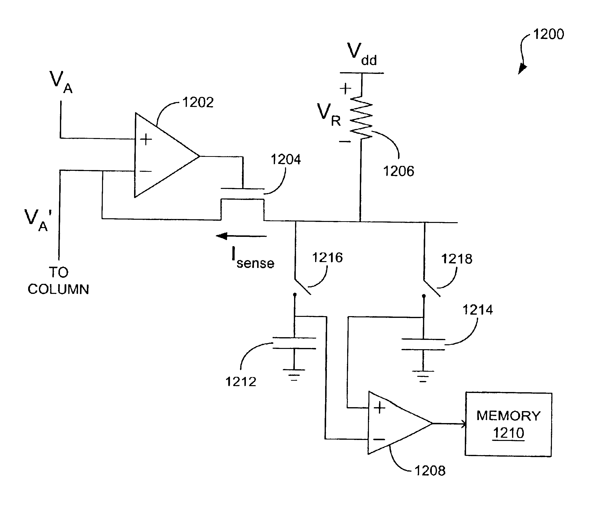
[0034]As identified above, known reading schemes used to read from cross-point array magnetic memory devices typically waste a relatively large amount of current and therefore power. Disclosed herein are reading schemes that significantly reduce the amount of power that is used to read from such memory devices. As is discussed in greater detail below, the reading schemes each involve the application of an array voltage, VA, to the array for a short period of time so that the voltage is merely pulsed on and off. This pulsing of the array voltage, VA, translates to substantial power savings.

[0035]Referring now to the drawings, in which like numerals indicate corresponding parts throughout the several views, FIG. 9 illustrates a portion of a cross-point array magnetic memory device 900 that, for instance, can comprise a magnetic random access memory (MRAM) device. The device 900 includes an array of memory cells 902. Although a limited number of memory cells 902 is depicted in FIG. 9, ...


PUM


Abstract

Power-saving reading of magnetic memory devices. In one arrangement, a method includes pulsing a voltage on the array, and obtaining a voltage value indicative of a memory state of the target memory cell from the voltage pulse using a sensing circuit that is electrically connected to the target memory cell. In another arrangement, a method includes pulsing an array voltage on a plurality of row and column conductors of the array, connecting a sensing circuit to a conductor that is electrically coupled to the target memory cell, the sensing circuit including a sense element, and determining the voltage drop across the sense element of the sensing circuit during the voltage pulse, the voltage drop being indicative of a memory state of the target memory cell.

Description

FIELD OF THE INVENTION[0001]The present disclosure relates to memory devices. More particularly, the disclosure relates to power-saving reading of magnetic memory devices.BACKGROUND OF THE INVENTION[0002]Magnetic memory such as magnetic random access memory (MRAM) is a non-volatile, semiconductor-based memory technology in which magnetic, rather than electrical, charges are used to store bits of data.[0003]Typically, magnetic memory devices comprise a plurality of memory cells or bits that are arranged in a two-dimensional array. Each memory cell is configured to store a single bit of information, i.e., a logic value “1” or a logic value “0.” Each memory cell of the array is coupled to a column conductor and a row conductor at a cross-point of the conductors.[0004]To write data to a target memory cell, current flow is provided through the column conductor and row conductor associated with the target memory cell. The magnetic fields created by the flow of electrons through the conduc...

Claims


Application Information

Patent Timeline
Patent Type & Authority Patents(United States)
IPC IPC(8): G11C11/16G11C11/02G11C7/06
CPCG11C7/062G11C11/16G11C13/0061G11C27/022G11C2013/0057G11C11/1673
Inventor SMITH, KENNETH KAYPERNER, FREDERICK A.
Owner SAMSUNG ELECTRONICS CO LTD
Why Eureka
Try Eureka