Oblique angled suspension caster fork for wheelchairs

a caster fork, oblique angled technology, applied in the field of shock absorption, can solve the problems of complete component failure, premature wheelchair frame deterioration, caster fork design has so far had drawbacks related to functionality, efficiency, durability and aesthetics

Inactive Publication Date: 2005-05-17
THE GOVERNMENT OF THE UNITED STATES OF AMERICA AS REPRESENTED BY THE DEPT OF VETERANS AFFAIRS
View PDF28 Cites 14 Cited by
  • Summary
  • Abstract
  • Description
  • Claims
  • Application Information

AI Technical Summary

Benefits of technology

[0011]The invention solves the problems, and overcomes the drawbacks and disadvantages of the prior art shock absorption systems by

Problems solved by technology

Additionally, common wheelchair component durability issues include premature wheelchair frame deterioration, or complete component failure due to fatigue.
However, such caster fork designs have thus far had drawbacks related to functionality, efficiency, durability and aesthetics.
Herold however does not address shock absorption for wheelchair and other related applications, in which the impact forces are relatively large in the vertical and horizontal directions.
Moreover, the rubber block for Herold only ab

Method used


Image

  • Oblique angled suspension caster fork for wheelchairs
  • Oblique angled suspension caster fork for wheelchairs
  • Oblique angled suspension caster fork for wheelchairs

Examples


first embodiment

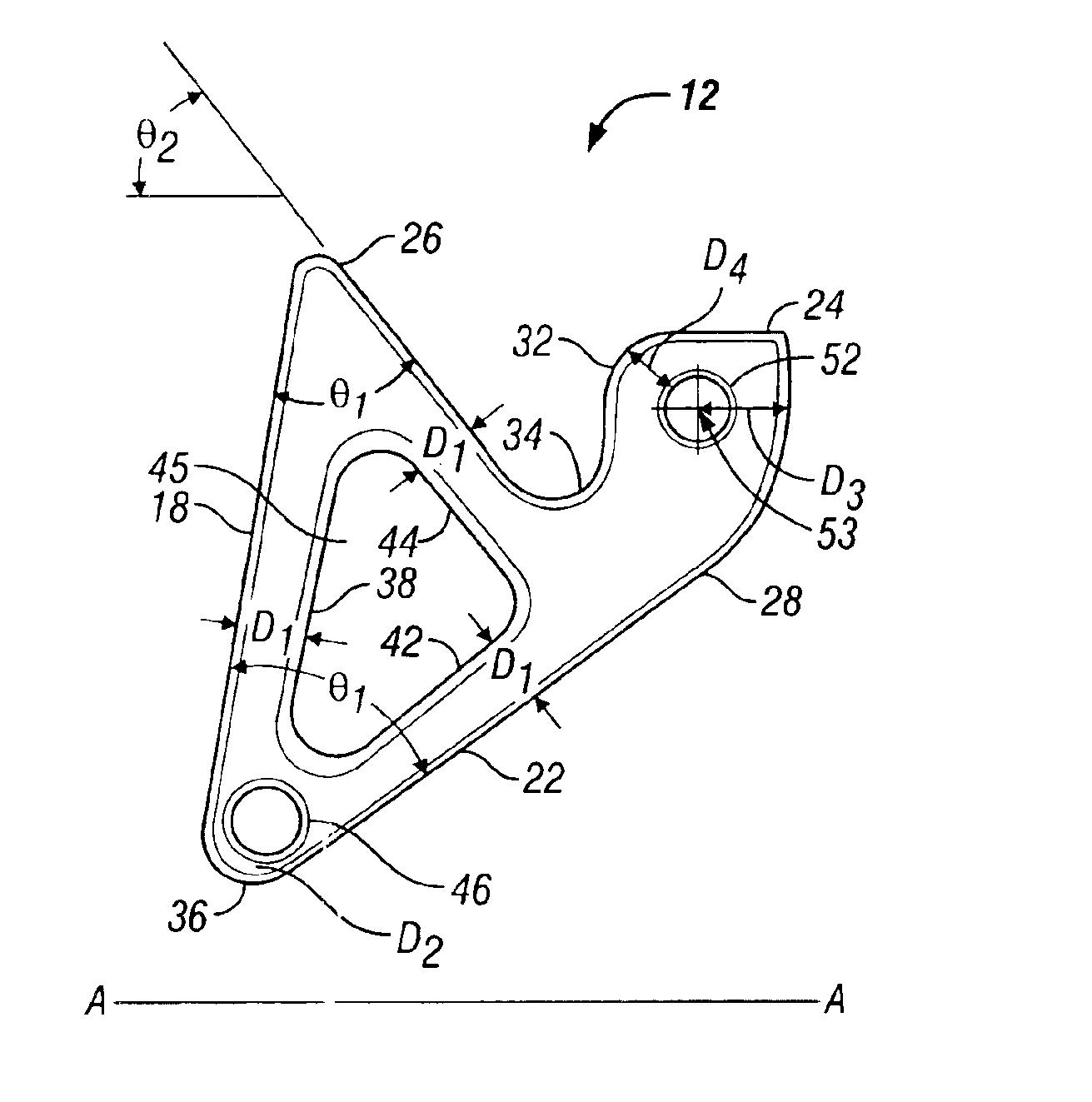
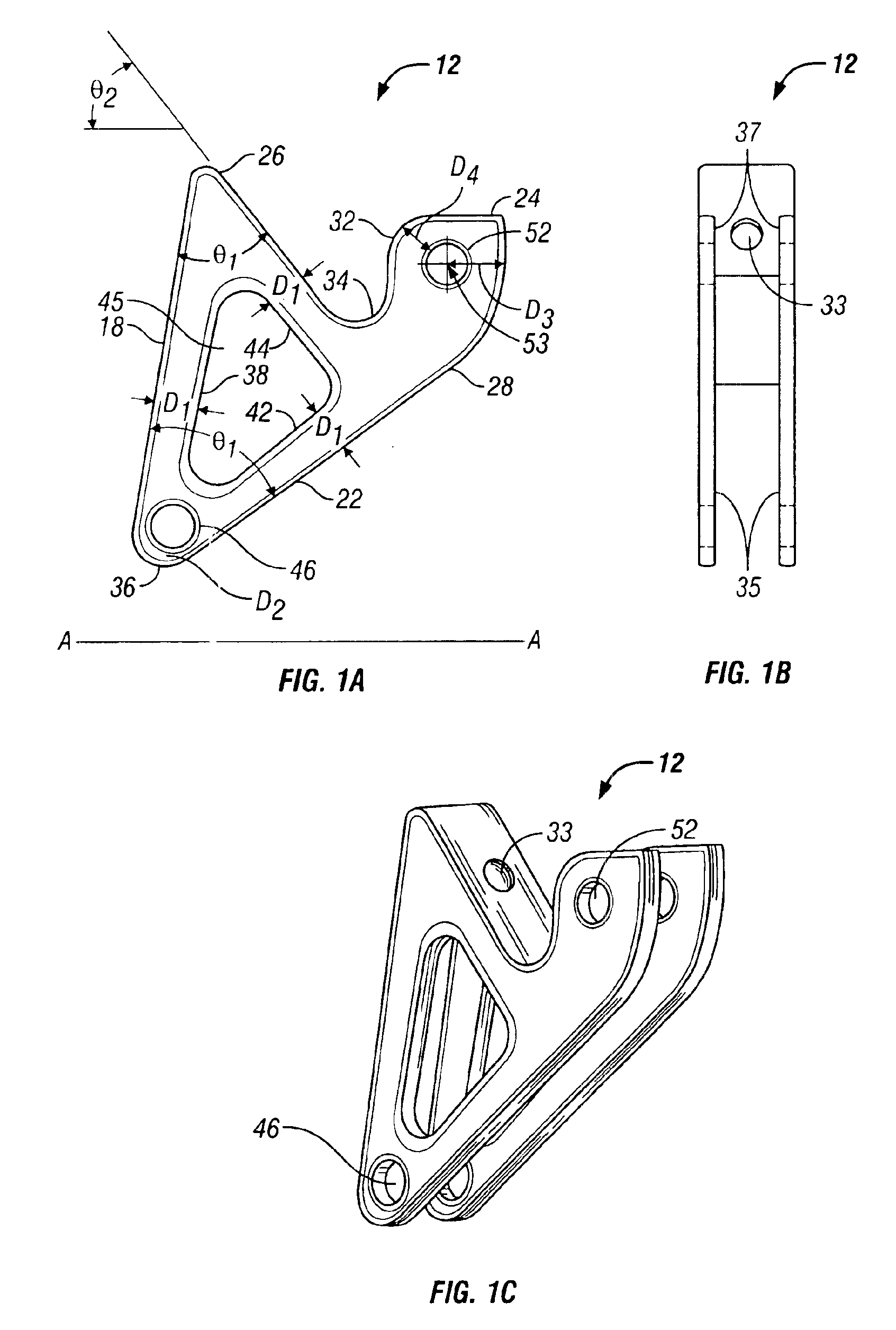
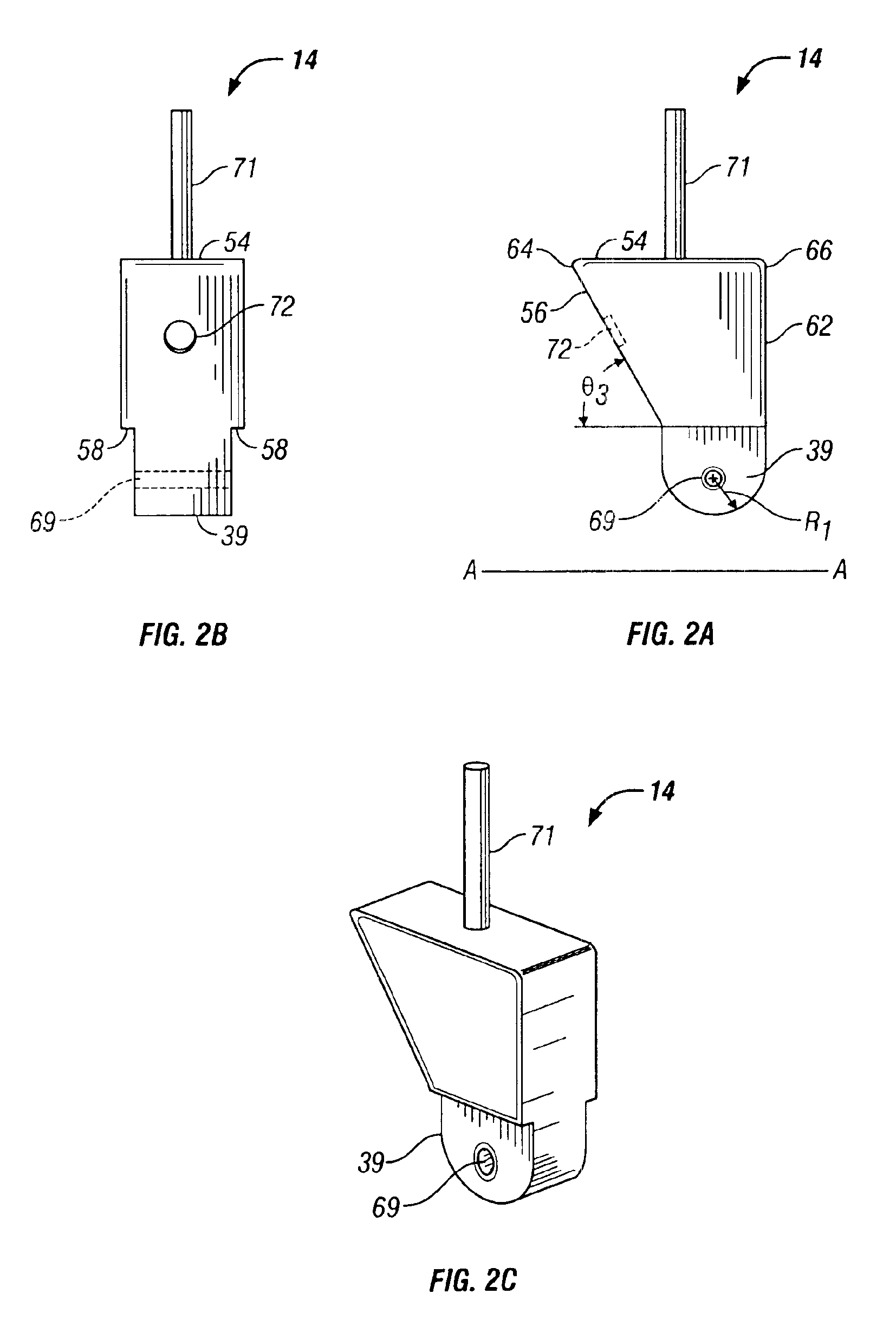
[0036]Referring now to the drawings wherein like reference numerals designate corresponding parts throughout the several views, FIGS. 1A-4 illustrate a shock absorption mechanism according to the present invention, generally designated 10. Shock absorption mechanism 10 may generally include a caster fork 12, a joint 14 and a shock absorber 16.

[0037]Referring to FIGS. 1A-1C and 4, caster fork 12 may include first through fourth generally flat surfaces 18, 22, 24 and 26, respectively. It is foreseeable that surfaces 18, 22, 24 and 26 may be curved. In the orientation of shock absorption mechanism 10 of FIG. 4, surface 24 is oriented generally parallel to a generally horizontal plane-A of travel for wheel 20 affixed to a wheelchair (not shown). Alternatively, it is foreseeable that surface 24 may be disposed in an oblique configuration relative to generally horizontal plane-A. Surface 18 may be oriented at a generally acute angle θ1 relative to surfaces 22 and 26. Likewise, surface 26 ...

second embodiment

[0060]a shock absorption mechanism according to the present invention will now be described in detail.

[0061]Referring to FIGS. 8 and 9, the second embodiment of shock absorption mechanism, generally designated 80, is illustrated. Shock absorption mechanism 80 may generally include caster fork 82, joint 84, piston 86 disposed within cylinder 88 and wheel 90.

[0062]For shock absorption mechanism 80, caster fork 82 and joint 84 may be generally configured similar to caster fork 12 and joint 14 for shock absorption mechanism 10, illustrated in FIGS. 1A-4.

[0063]Specifically, referring to FIGS. 1A-1C and 8, caster fork 82 may generally be identical to caster fork 12, except that indentation 33 on caster fork 12 may be omitted for caster fork 82. Additionally, instead of generally flat surface 26, surface 92 of caster fork 82 may include a generally curved profile for facilitating engagement with piston 86.

[0064]Caster fork 82 may be constructed of rigid metals such as steel or aluminum, or...


PUM


Abstract

A shock absorption mechanism for a wheelchair includes a caster fork including a first oblique surface and a second horizontally disposed surface, relative to a horizontal plane of travel of the wheelchair. A portion of the second surface includes a curved profile. A joint is mountable adjacent a first section thereof to a frame of the wheelchair and adjacent a second section thereof to the caster fork. The joint includes a first oblique surface and a second surface for guiding reciprocation of the curved profile portion of the caster fork. A shock absorber is disposed in an oblique orientation between the first oblique surface of the caster fork and the first oblique surface of the joint. The caster fork is pivotable adjacent the second section of the joint. The shock absorber is compressable in a direction generally parallel to the oblique orientation thereof during pivoting of the caster fork.

Description

RELATED APPLICATIONS[0001]This application claims benefit of priorty of Provisional Application Ser. No. 60 / 338,577, filed Dec. 11, 2001.BACKGROUND OF INVENTION[0002]a. Field of Invention[0003]The invention relates generally to shock absorption, and, more particularly to an improved apparatus and method for the absorption of horizontal and vertical impact forces in a wheelchair during travel over rough or uneven surfaces.[0004]b. Description of Related Art[0005]Wheelchairs include various components which are subject to high impact forces that directly affect wheelchair comfort and durability. In order to improve wheelchair ride and comfort, and to avoid secondary injuries due to extended wheelchair use, wheelchair components must be designed to eliminate or reduce the effect of such impact forces. Common secondary injuries due to extended wheelchair use include, for example, musculoskeletal injuries such as herniated discs, spinal deformities and chronic low back pain, as well as n...

Claims


Application Information

Patent Timeline
IPC IPC(8): B60B33/04
CPCB60B33/045Y10T16/214Y10T16/196Y10T16/212
Inventor COOPER, RORY A.AMMER, WILLIAMMCCARTNEY, MARKBLAUCH, COREY
Owner THE GOVERNMENT OF THE UNITED STATES OF AMERICA AS REPRESENTED BY THE DEPT OF VETERANS AFFAIRS
Why Eureka
Try Eureka