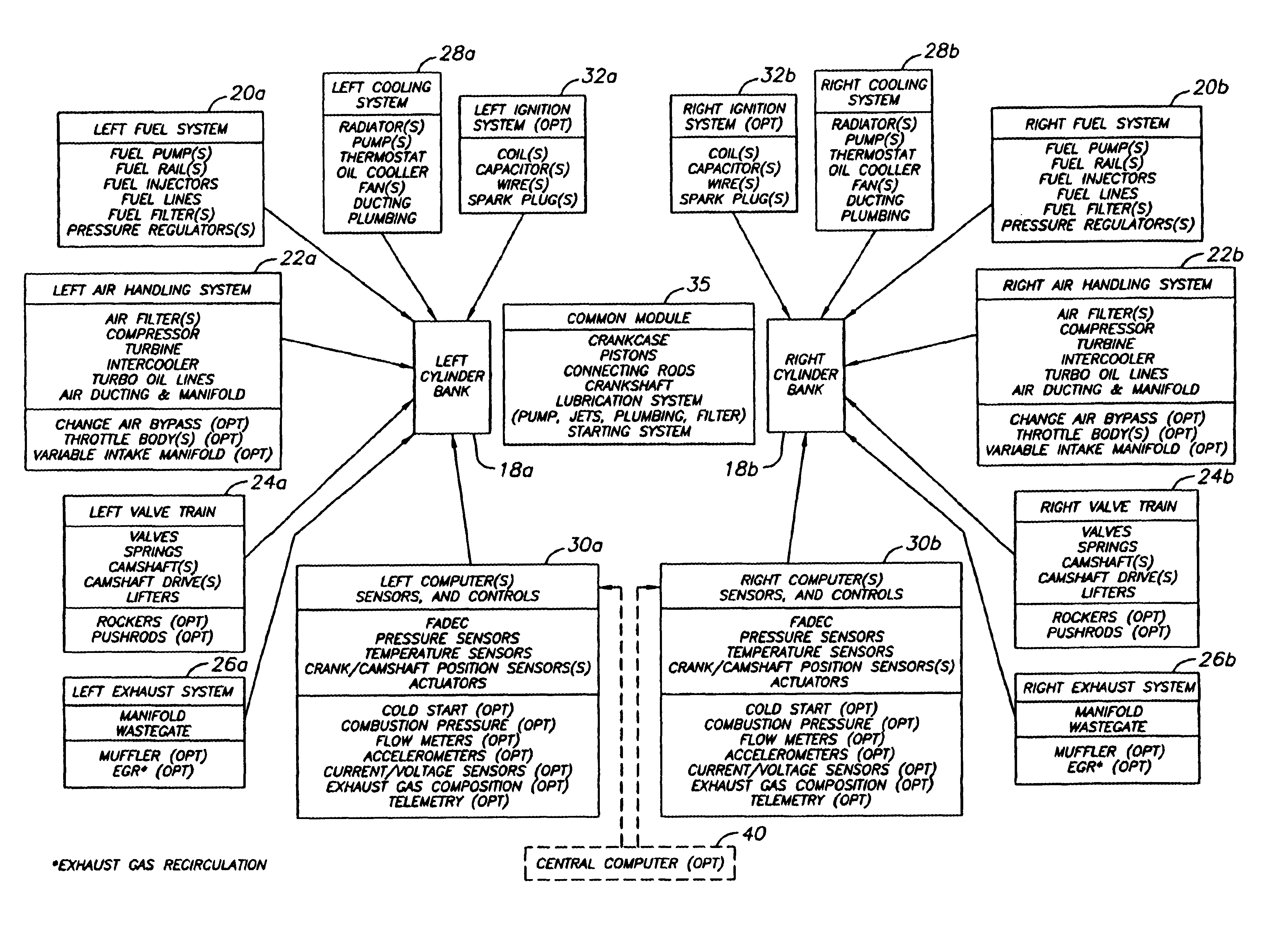
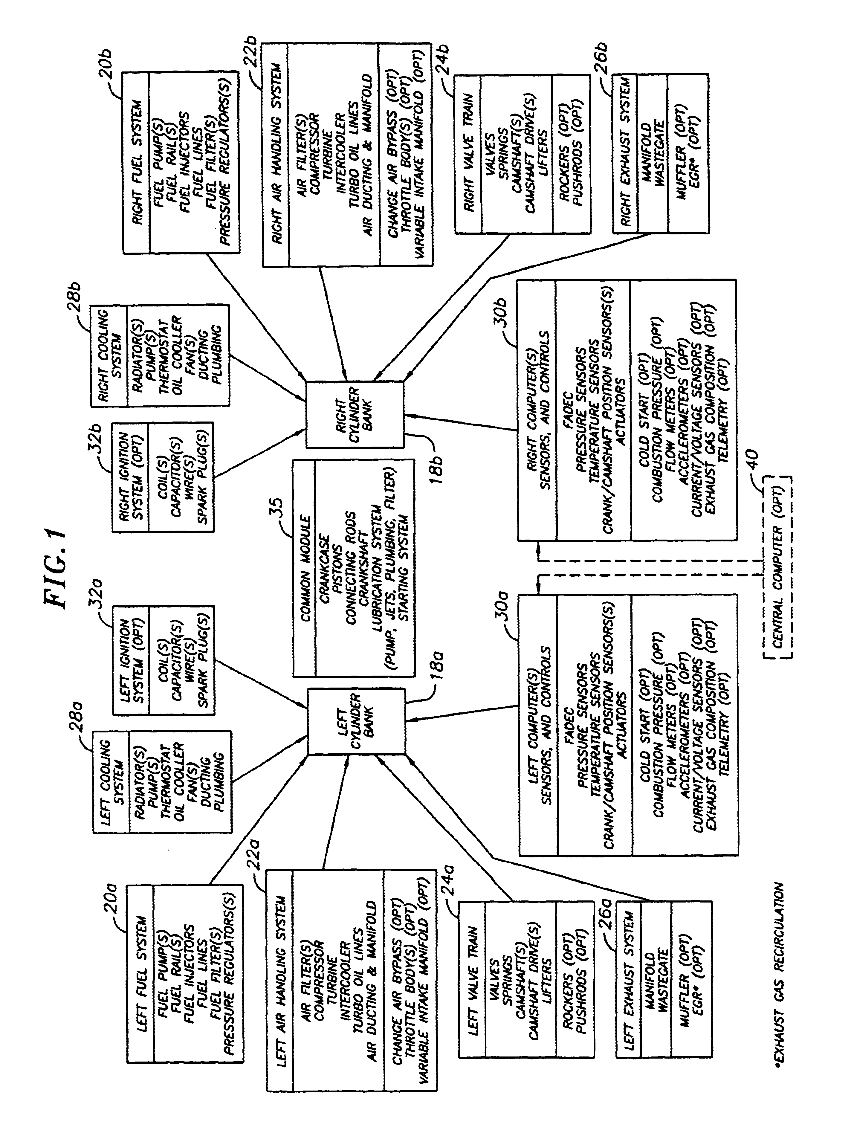
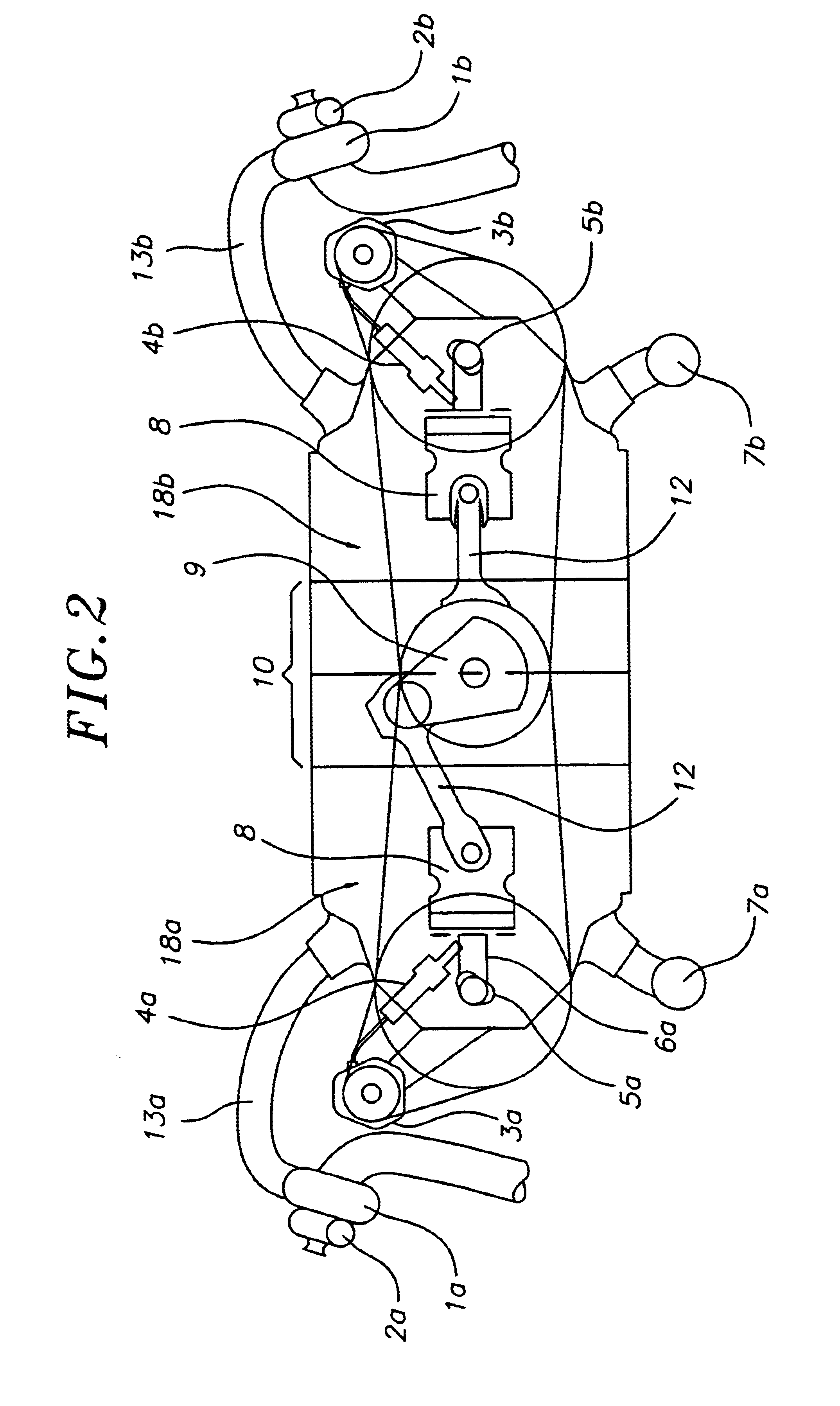
[0021]Modern high performance IC engines use multiple cylinders (or rotors in a rotary engine) to provide the required power and low vibration. Failures of these sophisticated engines are more likely to be a result of a subsystem failure than a result of a failure of the cranking mechanism, the lubrication system or the basic structure of the engine. To provide a higher powerplant reliability, the present invention does not combine multiple engines, but provides a single engine system which continues to operate at partial power after a single, or several, failure(s) of any and several subsystems except for the cranking system (pistons, connecting rods and crankshaft in the case of a piston engine, or rotors and rotor shaft in the case of a rotary engine), the lubrication system and the basic engine structure (crankcase, cylinder block(s) etc.). This fail operational mode in an exemplary embodiment engine system having two sets of subsystems is believed to provide 50% or more of full engine power and allows for a safe completion of the journey of the vehicle (aircraft, boat, etc.) or for a safe operation of a machine in which the powerplant is safety critical.
[0022]In an exemplary embodiment, a method for improving the reliability of an engine is provided. The method requires providing a single engine having an output shaft and first and second power producing members producing power driving the output shaft. The method also requires providing a first set of systems serving the first power producing member, and providing a second set of systems separated from the first set of systems and having the same type of systems as the first set of systems, the second set of systems serving the second power producing member, and operating the engine, whereby the power producing members drive the output shaft. Moreover, the method requires detecting degradation of a system of the first and second set of systems or degradation of one of the first and second power producing members, reducing a function of at least one system of the first and second sets of systems having the degraded system or serving the degraded power producing member, and continuing the operation of the engine with the power producing member served by the degraded system or the degraded power producing member producing a reduced power level relative to the other power producing member.
[0023]In another exemplary embodiment, a method for operating a single engine having an output shaft, a first power producing member and a second power producing member, where the first and second power producing members produce power to drive said output shaft, is provided. The method requires controlling the operation of a first fuel system providing fuel to operate the first power producing member, controlling the operation of a first set of systems serving the first power producing member, controlling the operation of a second fuel system providing fuel to operate the second power producing member, and controlling the operation of a second set of systems separate from the first set of systems and having systems of the same type as the first set of systems, the second set of systems serving the second power producing member. The method also requires detecting degradation of one system of the first and second set of systems or one of the power producing members, and reducing a function of at least one of the systems of the first and second set of systems for reducing the production of power by the power producing member served by the degraded system or by the degraded power producing member while maintaining the production of power by the other of the first and second power producing members and the continued operation of the engine.
[0024]In a further exemplary embodiment, a method for operating a single engine having an output shaft, a first power producing member and a second power producing member, where the first and second power producing members produce power to drive said output shaft, is provided. The method requires controlling the operation of a first set of systems serving the first power producing member, and controlling the operation of a second set of systems separate from the first set of systems and having the same type of systems as the first set of systems, the second set of systems serving the second power producing member. The method also requires detecting degradation of one system of the first and second set systems or of one of the first and second power producing members and reducing a function of at least one of the systems of said first and second set of systems serving the power producing member served by the degraded system or serving the degraded power producing member for reducing the production of power by the power producing member while maintaining the production of power by the other of the first and second power producing members and the continued operation of the engine.
[0038]In yet a further exemplary embodiment, an advanced high performance six-cylinder diesel engine, the complete subsystems including fuel systems, liquid cooling systems, valvetrains, turbochargers, wastegates, intercoolers, intake and exhaust manifolds, sensors, computers and electric wiring harnesses are in duplicates, one set for the left hand (LH) side of the horizontally-opposed engine and one set for the right hand (RH) side. Any failure of one or more of the LH side systems will allow the engine to continue part power operations on the RH side and vice-versa. With the failed side of the engine disabled (zero fuel injected) and the cranking and lubrication systems operational, the engine will produce 50% of full power at a slightly increased vibration level and specific fuel consumption. This will provide the same capability to continue the mission as provided by a two-engine propulsion system.
[0040]In the aerospace industry, the vast data accumulated during the last 5 decades regarding failures, reliability and flight safety were used to analyze the desirability of single-engine vs. two-engine in fighter aircraft and in helicopters. The complexity of the two-engines results in a larger and more expensive aircraft to achieve the same utility and performance. In addition, the two-engine aircraft requires more maintenance and has lower availability (being ready to fly when needed) than the single-engine aircraft. The present invention, by providing redundancy in selected engine subsystems, provides most of the reliability improvement of multiple engines while avoiding the majority of increased complexity weight, cost and maintenance of the multiple-engines. In addition, if a single output shaft is desired, the present invention avoids the added complexity, weight, cost and maintenance of the combining gearbox and clutching mechanism.


