Fluid flow distribution device

Inactive Publication Date: 2005-05-17
MODINE MFG CO
View PDF9 Cites 59 Cited by
  • Summary
  • Abstract
  • Description
  • Claims
  • Application Information

AI Technical Summary

Problems solved by technology

This can result in heat fluxes that vary significantly from flow path to flow path (i.e., from tube to tube) and can negatively affect performance and stability in the vaporizer.
For example, some such vaporizers do not lend themselves to be readily or easily manufactured from a variety of materials

Method used


Image

  • Fluid flow distribution device
  • Fluid flow distribution device
  • Fluid flow distribution device

Examples


Embodiment Construction

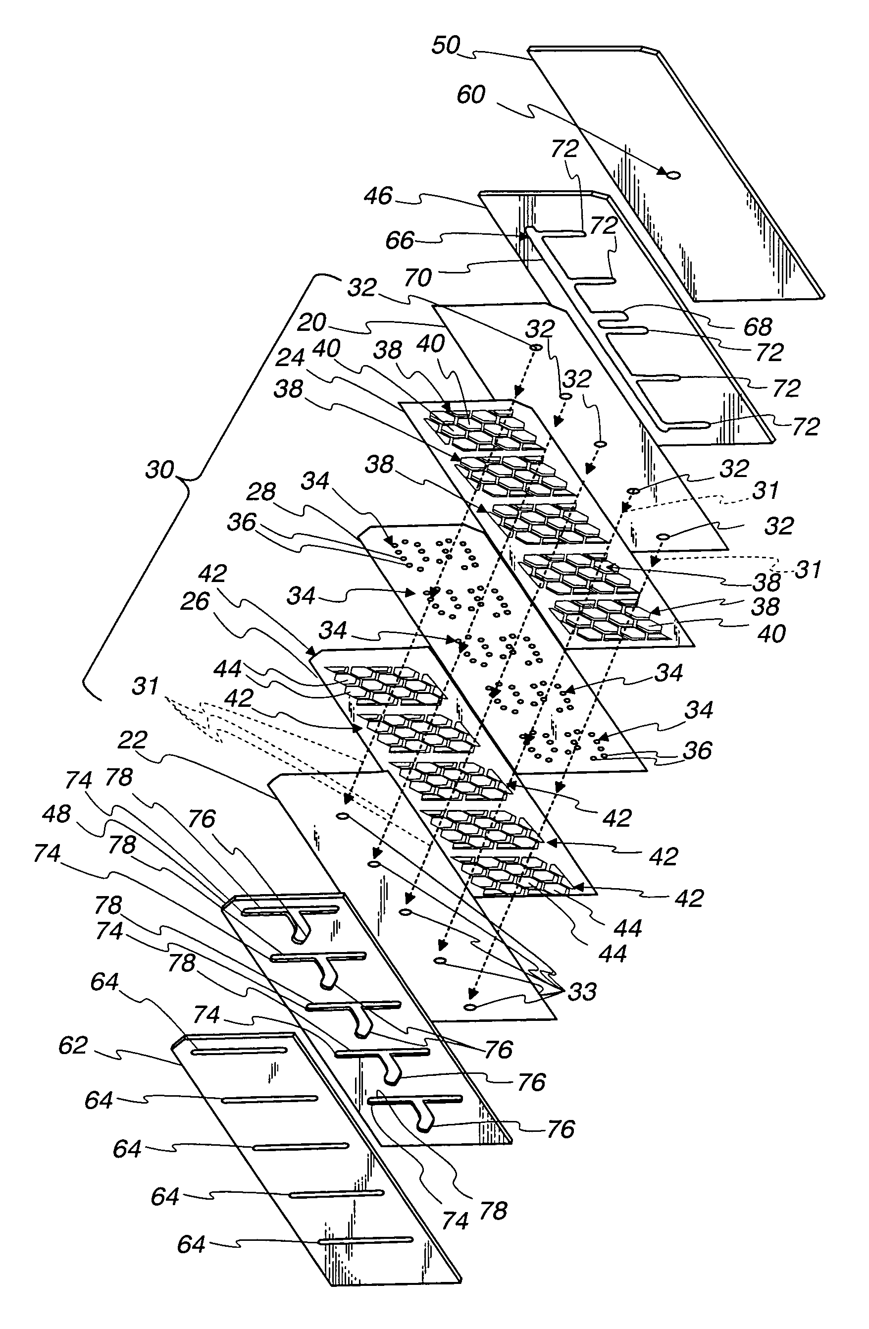
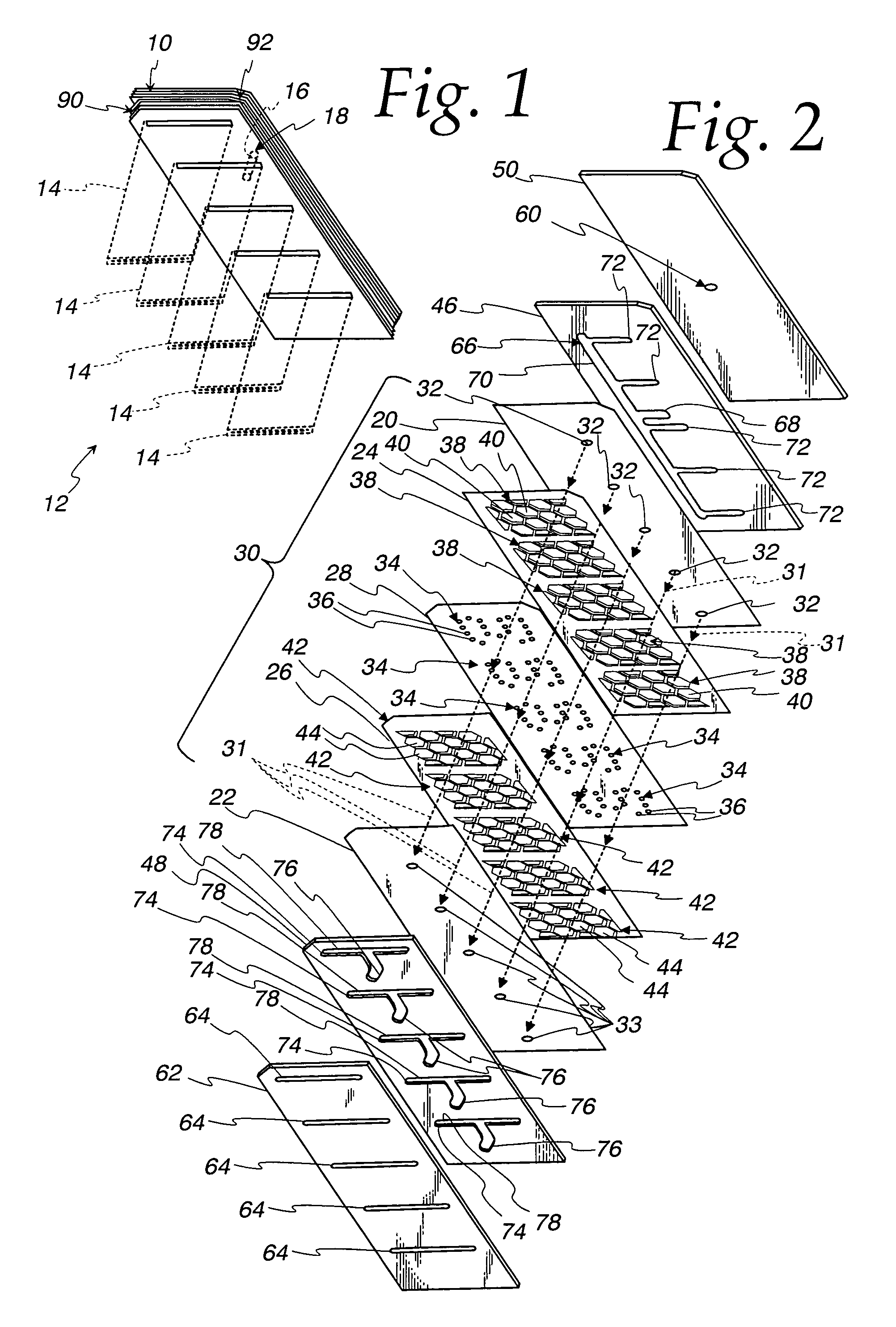
[0020]With reference to FIG. 1, a fluid flow distribution device 10 is shown in connection with a heat exchanger 12 having multiple parallel heat exchange flow paths or units 14 shown in the form of extruded, flattened multiport tubes (shown in phantom with only partial lengths). The heat exchanger 12 further includes a fluid inlet 16 (shown in phantom) that receives a fluid flow 18 that should, under ideal conditions, be equally distributed among the plurality of heat exchange units 14. The distributed fluid flow 18 passes through the interior ports of the tubes 14 for the transfer of heat to another fluid flow that is in heat exchange relation with the exterior of the tubes 14, typically through some suitable type of fin (not shown), such as serpentine fins extending between adjacent tubes or plate fins extending across all of the tubes 14. A collection manifold (not shown) for the fluid flow 18 will normally be provided on the opposite end of the heat exchange units 14 to collec...


PUM


Abstract

A fluid flow distribution device (10) is provided for use in a heat exchanger (12) having multiple heat exchange units (14) that receive a fluid flow (18) from an fluid inlet (16). The device includes a plurality of tortuous flow paths (31) to direct distributed portions of the fluid flow (18) from the inlet (16) to the heat exchange units (14). Each tortuous flow path (31) is defined by a pair of flow chamber plates (24,26), and an orifice plate (28) sandwiched between the flow chamber plates (24,26). Each tortuous flow path (31) includes a series (34) of orifices (36) extending through the orifice plate (28), a first pattern (38) of first flow chambers (40) formed in one of the flow chamber plates (24,26) and aligned with sequential pairs of the orifices (36), and a second pattern (42) of second flow chambers (44) formed in the other of the flow chamber plates (24,26) and offset with respect to the first pattern (38) and the pairs of orifices (36).

Description

FIELD OF THE INVENTION[0001]This invention relates to devices that distribute fluid flow from a common source to a plurality of flow paths, and in more particular applications to such devices as used in heat exchangers to equally distribute a fluid flow among a plurality of parallel heat exchange flow paths or units for passage therethrough in heat exchange relation with one or more other fluids.BACKGROUND OF THE INVENTION[0002]There are many fluid components that require a desired distribution, generally equal, of a fluid flow among multiple flow paths from a common fluid flow source. One example of such fluid flow components are heat exchangers, and particularly heat exchangers that act as evaporators or vaporizers. Because the heat absorbed by the liquid fluid that is being evaporated or vaporized is mostly latent heat, it is typical for the majority of length of such vaporizing heat exchangers to be occupied by a two phase fluid. Unlike some heat exchangers, for example condense...

Claims


Application Information

Patent Timeline
IPC IPC(8): F28F27/02F28F9/02F28F27/00
CPCF28F9/0278F28D1/053F28F9/02
Inventor VALENSA, JEROEN
Owner MODINE MFG CO
Why Eureka
Try Eureka