Method and apparatus for selective injection or flow control with through-tubing operation capacity

a flow control device and operation capacity technology, applied in the direction of rotary drilling, sealing/packing, borehole/well accessories, etc., can solve the problems of mechanical malfunction of such tools and obstacle to the proper functioning of the flow control devi

Inactive Publication Date: 2005-05-17
SCHLUMBERGER TECH CORP
View PDF39 Cites 25 Cited by
  • Summary
  • Abstract
  • Description
  • Claims
  • Application Information

AI Technical Summary

Benefits of technology

[0005]An in-line flow control device for a well chokes f

Problems solved by technology

This is sometimes referred to as “producing sand”, and can be undesirable for a number of reasons, including added production costs, and erosion of well tools within the completion, which could lead to the mechanical malfunctioning of such tools.
A drawback to gravel pack completions arises when it is desired to connect a remotely-controllable flow control device to the production tubing to regulate the flow of production fluids from the gravel-packed well annulus into the production tubing, or to regulate the flow of injection fluids from

Method used


Image

  • Method and apparatus for selective injection or flow control with through-tubing operation capacity
  • Method and apparatus for selective injection or flow control with through-tubing operation capacity
  • Method and apparatus for selective injection or flow control with through-tubing operation capacity

Examples


Embodiment Construction

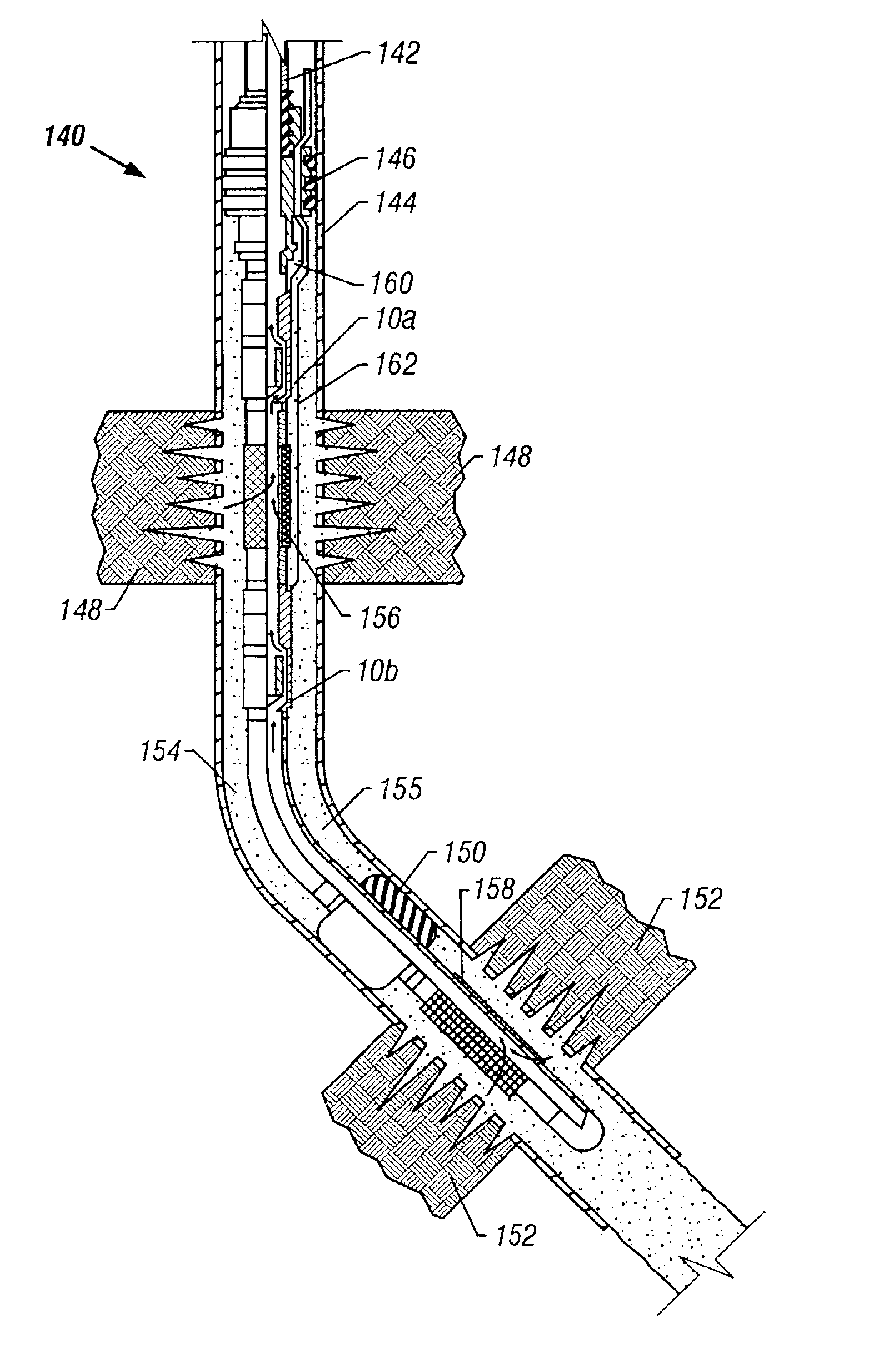
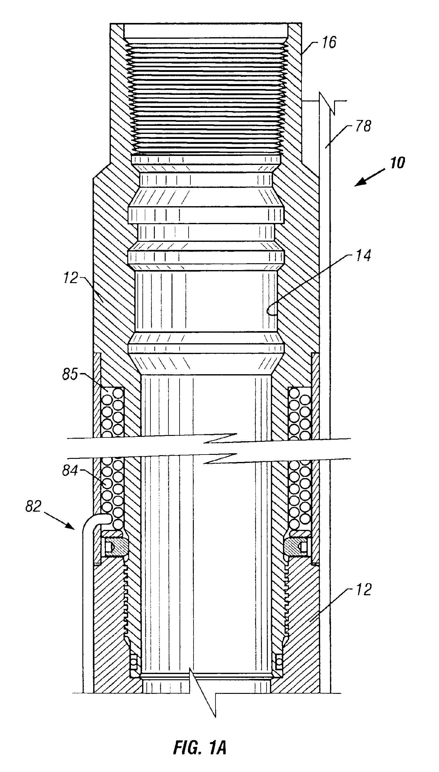
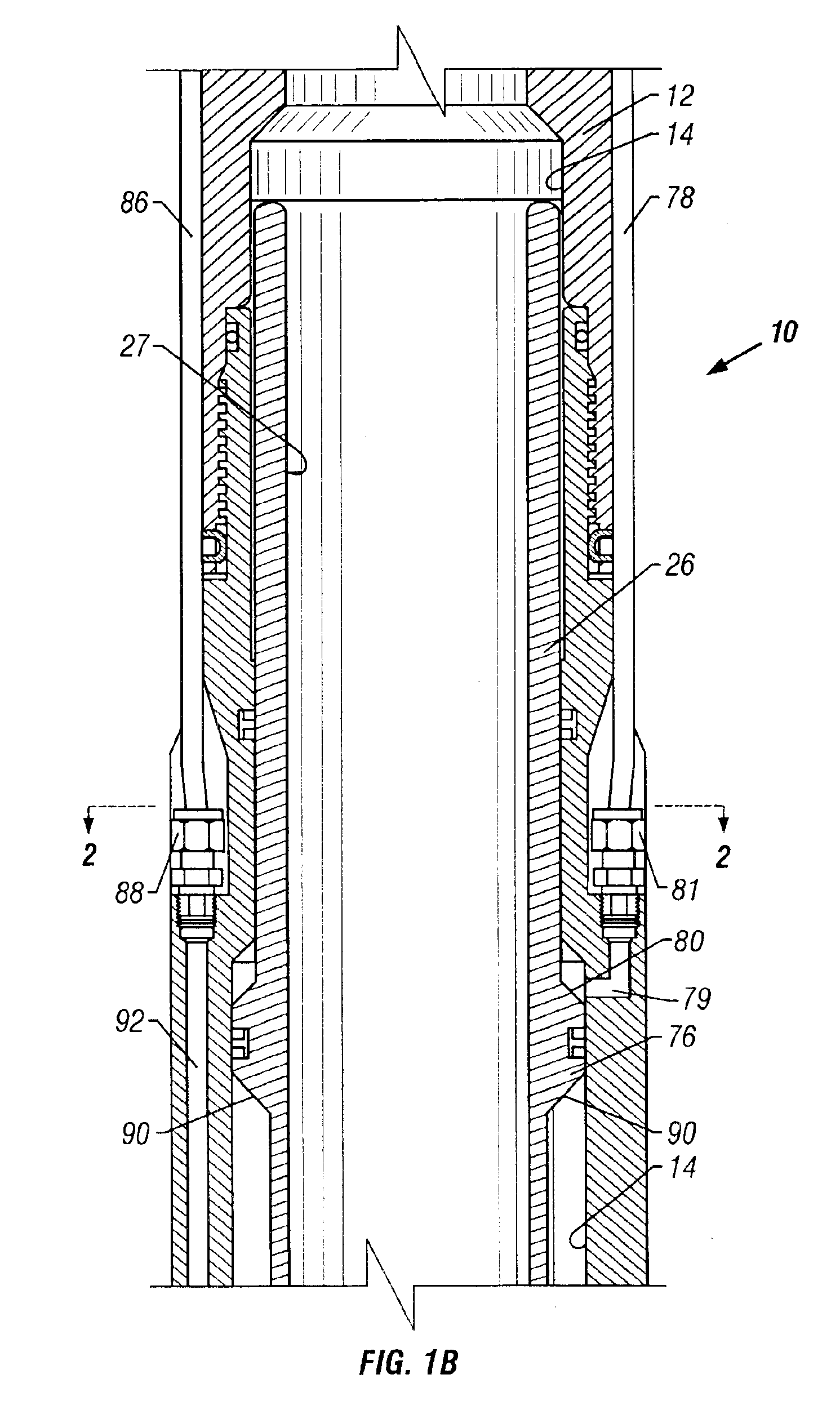
[0019]For the purposes of this description, the terms “upper” and “lower,”“up hole” and “downhole” and “upwardly” and “downwardly” are relative terms to indicate position and direction of movement in easily recognized terms. Usually, these terms are relative to a line drawn from an upmost position at the earth's surface to a point at the center of the earth, and would be appropriate for use in relatively straight, vertical wellbores. However, when the wellbore is highly deviated, such as from about 60 degrees from vertical, or horizontal, these terms do not make sense and therefore should not be taken as limitations. These terms are only used for ease of understanding as an indication of what the position or movement would be if taken within a vertical wellbore.

[0020]Referring to the drawings in detail, wherein like numerals denote identical elements throughout the several views, a specific embodiment of the downhole flow control device of the present invention is referred to genera...


PUM


Abstract

An in-line flow control device for a well chokes flow through a conduit while allowing access therethrough.

Description

RELATED APPLICATIONS[0001]The present application is a continuation-in-part of U.S. patent application Ser. No. 09 / 441,701 filed Nov. 16, 1999 now U.S. Pat. No. 6,631,767 which claims priority to U.S. Provisional application No. 60 / 108,810 filed Nov. 17, 1998.FIELD OF INVENTION[0002]The present invention relates to subsurface well equipment and, more particularly, to a method and apparatus for remotely controlling injection or production fluids in well completions which may include gravel pack.DESCRIPTION OF THE RELATED ART[0003]As is well known to those skilled in the art, certain hydrocarbon producing formations include sand. Unless filtered out, such sand can become entrained or commingled with the hydrocarbons that are produced to the earth's surface. This is sometimes referred to as “producing sand”, and can be undesirable for a number of reasons, including added production costs, and erosion of well tools within the completion, which could lead to the mechanical malfunctioning...

Claims


Application Information

Patent Timeline
IPC IPC(8): E21B23/00E21B34/00E21B34/10E21B43/02E21B43/04E21B43/00E21B43/14
CPCE21B23/006E21B34/101E21B43/04E21B43/14E21B34/102E21B2034/005E21B2200/05
Inventor PRINGLE, RONALD E.MORRIS, ARTHUR J.
Owner SCHLUMBERGER TECH CORP
Why Eureka
Try Eureka