
Doubly constrained robust capon beamformer

a beamformer and robust technology, applied in direction finders, instruments, antennas, etc., can solve the problems of steering vector error, general steering vector error, and capon beamformer performance can become worse than standard beamformers

Inactive Publication Date: 2005-05-17
FLORIDA UNIV OF A FLORIDA +1
View PDF0 Cites 4 Cited by
  • Summary
  • Abstract
  • Description
  • Claims
  • Application Information

AI Technical Summary

Benefits of technology

"The patent describes a method for enhanced Capon beamforming, which involves estimating the direction of arrival of a signal of interest (SOI) using a sensor array. The method includes steps to constrain the array steering vector, which is the vector that controls the direction of the sensor array, using a spherical uncertainty set and a constant norm constraint. The method also involves solving a matrix fitting relation to obtain an estimate of the array steering vector, which is used to determine the power of the SOI and the direction of arrival of the SOI. The invention can be used in radar, cellular communications, sonar, and acoustic imaging systems. The technical effect of the invention is to improve the accuracy and reliability of signal detection and imaging in various sensor systems."

Problems solved by technology

This results in steering vector error.
Steering vector error generally occurs because of differences between the assumed SOI arrival angle and the true SOI arrival angle and between the assumed array response and the true array response, such as due to array calibration errors.
Whenever the SOI steering vector error becomes significant, the performance of the Capon beamformer can become worse than standard beamformers.
However, these constraints are not explicitly related to the uncertainty of the array steering vector.
Moreover, for every additional linear constraint imposed, the beamformer loses one degree of freedom (DOF) for interference suppression.
However, for most of these methods, it is not clear how to choose the diagonal loading based on the uncertainty of the array steering vector.
Hence they are sensitive to the imprecise knowledge of the noise covariance matrix in addition to the array steering vector error.
Making these methods robust against the array steering vector error will not cure their sensitivity to imprecise knowledge of the noise covariance matrix.
However, even Capon methods which make explicit use of an uncertainty set of the array steering vector are computationally inefficient and cannot generally provide accurate power estimates for signals of interest.

Method used


Image

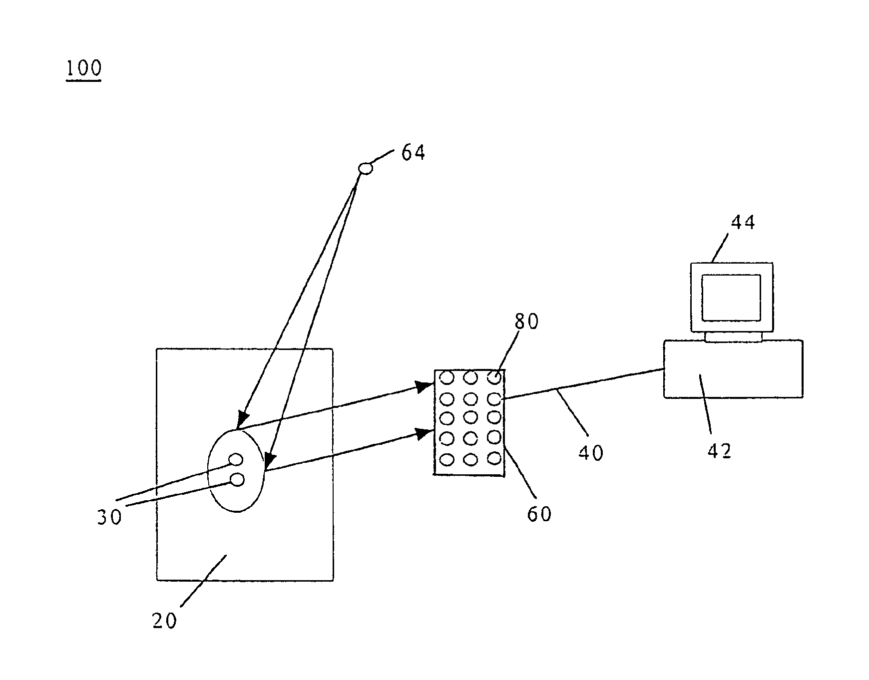
  • Doubly constrained robust capon beamformer
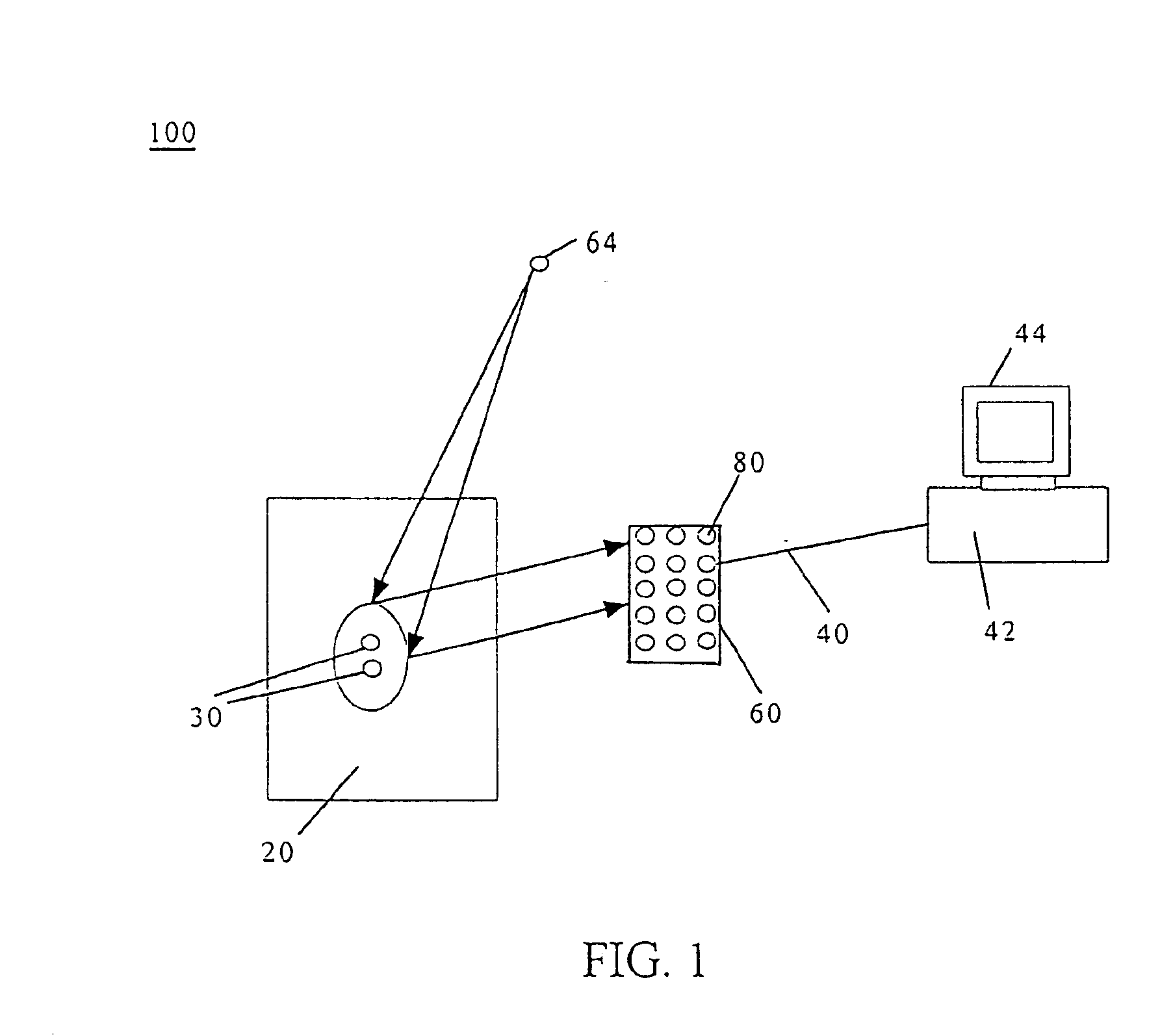
  • Doubly constrained robust capon beamformer
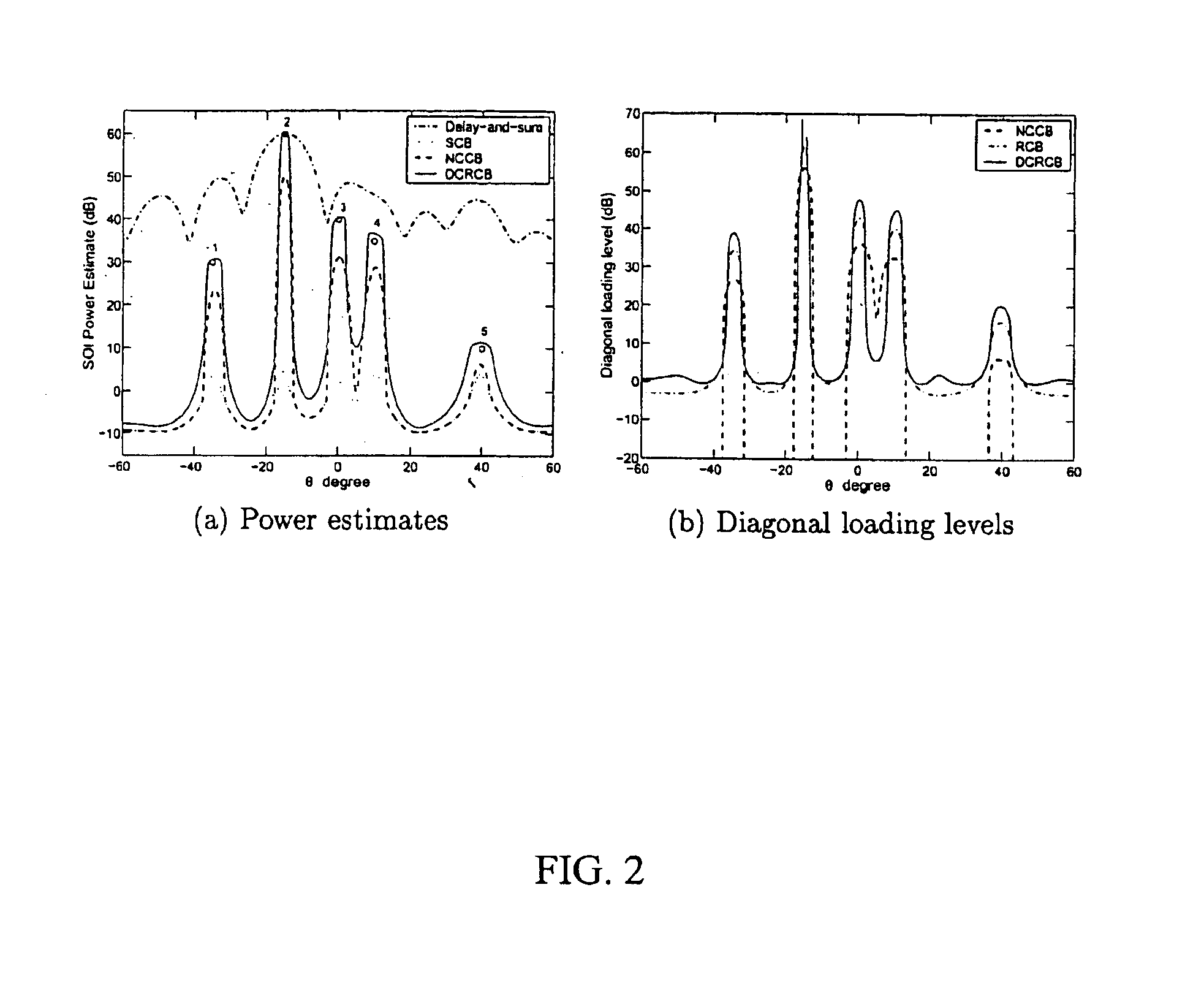
  • Doubly constrained robust capon beamformer

Examples


examples

[0059]It should be understood that the examples and embodiments described herein are for illustrative purposes only and that various modifications or changes in light thereof will be suggested to persons skilled in the art and are to be included within the spirit and purview of this application. The invention can take other specific forms without departing from the spirit or essential attributes thereof.

[0060]Numerical examples are provided in this section to compare the performances of the delay-and-sum beamformer, SCB, NCCB, RCB and the DCRCB according to the present invention. In all of the examples considered below, a uniform linear array with M=10 sensors and half-wavelength sensor spacing is assumed having a spatially white Gaussian noise covariance matrix given by Q=I.

[0061]For NCCB, ζ=βM,

where β(β≧1) is set as a user parameter. The larger the β, the closer NCCB is to SCB. On the other hand, the smaller the β, the closer NCCB is to the delay-and-sum beamformer. When β=1, the ...


PUM


Abstract

A method for enhanced Capon beamforming includes the steps of providing a sensor array including a plurality of sensor elements where an array steering vector corresponding to a signal of interest (SOI) is unknown. A covariance matrix fitting relation is bounded for the unknown array steering vector by constraining the array steering vector using a constant norm and a spherical uncertainty set. The matrix fitting relation is then solved to provide an estimate of said array steering vector.

Description

STATEMENT REGARDING FEDERALLY SPONSORED RESEARCH OR DEVELOPMENT[0001]The United States Government has rights in this invention pursuant to National Science Foundation grants CCR-0104887 and ECS-0097636.CROSS-REFERENCE TO RELATED APPLICATIONS[0002]Not applicable.FIELD OF THE INVENTION[0003]The invention relates to Capon beamforming, and more specifically to an advanced Capon beamforming method and related apparatus which provides computational efficiency and power estimates for signals of interest which can be adjusted for steering vector uncertainty.BACKGROUND[0004]Beamforming is a ubiquitous task in array signal processing, such as for radar, sonar, acoustics, astronomy, seismology, communications, and medical imaging. The standard data-independent beamformers include the delay-and-sum approach as well as methods based on various data-independent weight vectors for sidelobe control. The data-dependent Capon beamformer adaptively selects the respective weight vectors to minimize the...

Claims


Application Information

Patent Timeline
Patent Type & Authority Patents(United States)
IPC IPC(8): H01Q3/22H01Q3/26
CPCH01Q3/26H01Q3/22G01S7/52047G01S15/8915G10K11/346
Inventor LI, JIANSTOICA, PETREWANG, ZHISONG
Owner FLORIDA UNIV OF A FLORIDA
Learn More