Walkaway tomographic monitoring

a tomographic monitoring and walkaway technology, applied in the field of interpretation of reservoir monitoring, can solve the problems of higher power output, change in seismic velocity, and fluid pressure in the reservoir change,

Inactive Publication Date: 2005-05-17
BAKER HUGHES INC
View PDF12 Cites 29 Cited by
  • Summary
  • Abstract
  • Description
  • Claims
  • Application Information

AI Technical Summary

Problems solved by technology

In addition, there may also be changes in the pressure of the fluids in the reservoir.
Fluid substitution as well as pressure changes are known to cause changes in seismic velocities.
Other sources such as explosive or implosive sources, downhole airguns, and sparkers generally have higher power output and are more likely to cause damage to the wellbore.
This low-power limitation restricts utilization of crosswell seismic tomography to situations in which the interwell distance is relatively short (i.e., no more than about 1,000 feet).
Another limitation on the use of crosswell seismic tomography is the substantial costs associated with preparing the wells for deployment of downhole seismic sources and receivers.
In most cases, the diameters of the downhole seismic sources and receivers are too large to fit into the production tubing used to convey fluids from the reservoir to the surface.
Associated with the removal of production tubing is the cost of shutting down production for the seismic study.
One of the problems with crosswell tomography (real or simulated) is that the ray paths cover only a limited range of angles and there is a serious lack of near vertical raypaths.

Method used


Image

  • Walkaway tomographic monitoring
  • Walkaway tomographic monitoring
  • Walkaway tomographic monitoring

Examples


Embodiment Construction

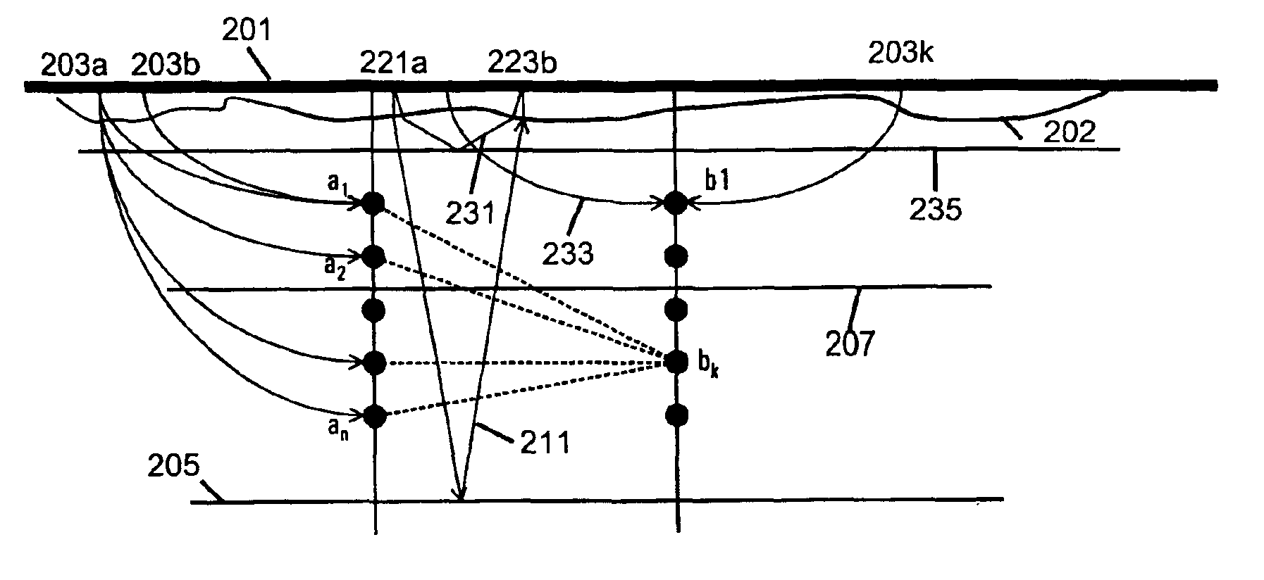
[0020]The method of acquiring data for reservoir monitoring according to the present invention is schematically illustrated in FIG. 4. The data acquisition comprises three main features. As in Blakeslee, receivers a1 . . . an and b1 . . . bn are deployed in two wells. Only two wells are shown to simplify the illustration and in reality, more wells could be used. Using surface seismic sources, depicted by 203a, 203b . . . 203k, crosswell seismic data are simulated using the method described in Blakeslee. However, contrary to the teachings of Blakeslee, surface sources are also deployed between the two wells. This provides additional rays for tomographic reconstruction for the region between the two wells and addresses the problem of limited aperture with conventional or simulated crosswell tomography. An exemplary raypath for such a source between the two well locations is depicted by 233. Again, for simplifying the figure, only one raypath is shown from a single source to a single d...


PUM


Abstract

Surface seismic sources are used to simulate crosswell data between the two wells, and, using surface receivers, reflection seismic data are obtained over the region between the two wells. Reflection data are preferably obtained from reflectors both above and below the reservoir. Tomographic analysis of the simulated crosswell and reflection data gives a model of the reservoir. Changes in the model are indicative of reservoir fluid changes, pressure changes, or compaction.

Description

BACKGROUND OF THE INVENTION[0001]1. Field of the Invention[0002]The invention is related generally to the field of interpretation of reservoir monitoring using time-lapse seismic measurements. More specifically, the present invention is directed towards a novel configuration of sources and receivers for providing improved tomographic reconstruction of reservoir images.[0003]2. Background of the Art[0004]Geophysical surveys are used to discover the extent of subsurface mineral deposits such as oil, natural gas, water, sulphur, etc. Geophysical methods may also be used to monitor changes in the deposit, such as depletion resulting from production of the mineral over the natural lifetime of the deposit which may be many years. The usefulness of a geophysical study depends on the ability to quantitatively measure and evaluate some geophysical analogue of a petrophysical parameter that is directly related to the presence of the mineral under consideration.[0005]Conventional crosswell sei...

Claims


Application Information

Patent Timeline
Patent Type & Authority Patents(United States)
IPC IPC(8): G01V1/40
CPCG01V1/42
Inventor ARONSTAM, PETER
Owner BAKER HUGHES INC
Why Eureka
Try Eureka