[0004]It is therefore an object of the present invention to provide a recordable optical disk and an optical disk recording device which can reliably prevent recording at speeds beyond predetermined limit values unique to the optical disk and thereby permit recording on the optical disk with minimized errors.
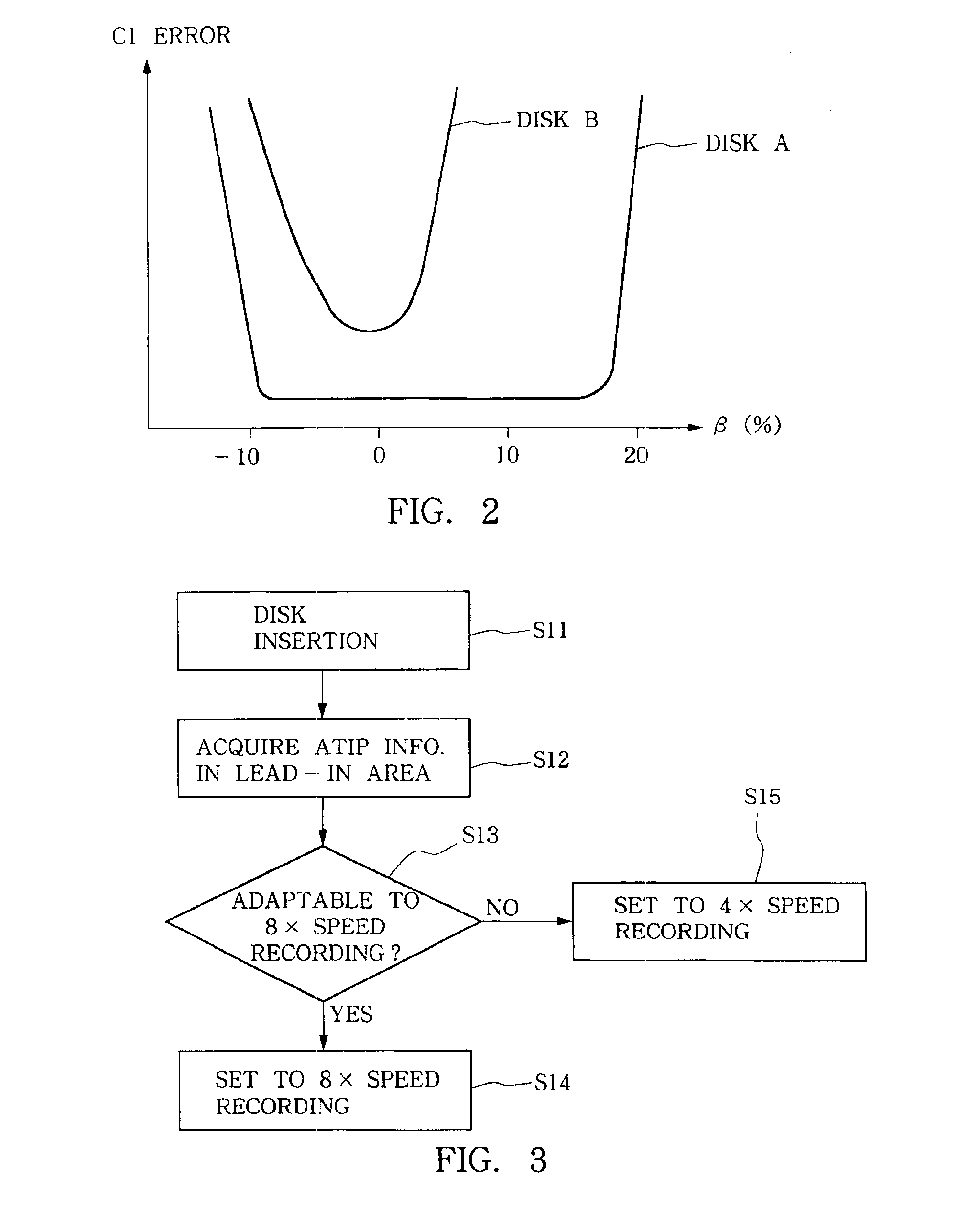
[0005]In order to accomplish the above-mentioned object, the present invention provides a recordable optical disk characterized in that disk-applicable-recording-speed information, i.e., information indicative of recording speeds suitably applicable to the optical disk, is pre-recorded on a disk's track during manufacture of the optical disk. Thus, by reading out the disk-applicable-recording-speed information from the track prior to recording, the actual recording speed for the optical disk can be set to a speed value within a range of the disk-applicable recording speeds, which permits recording with minimized errors.
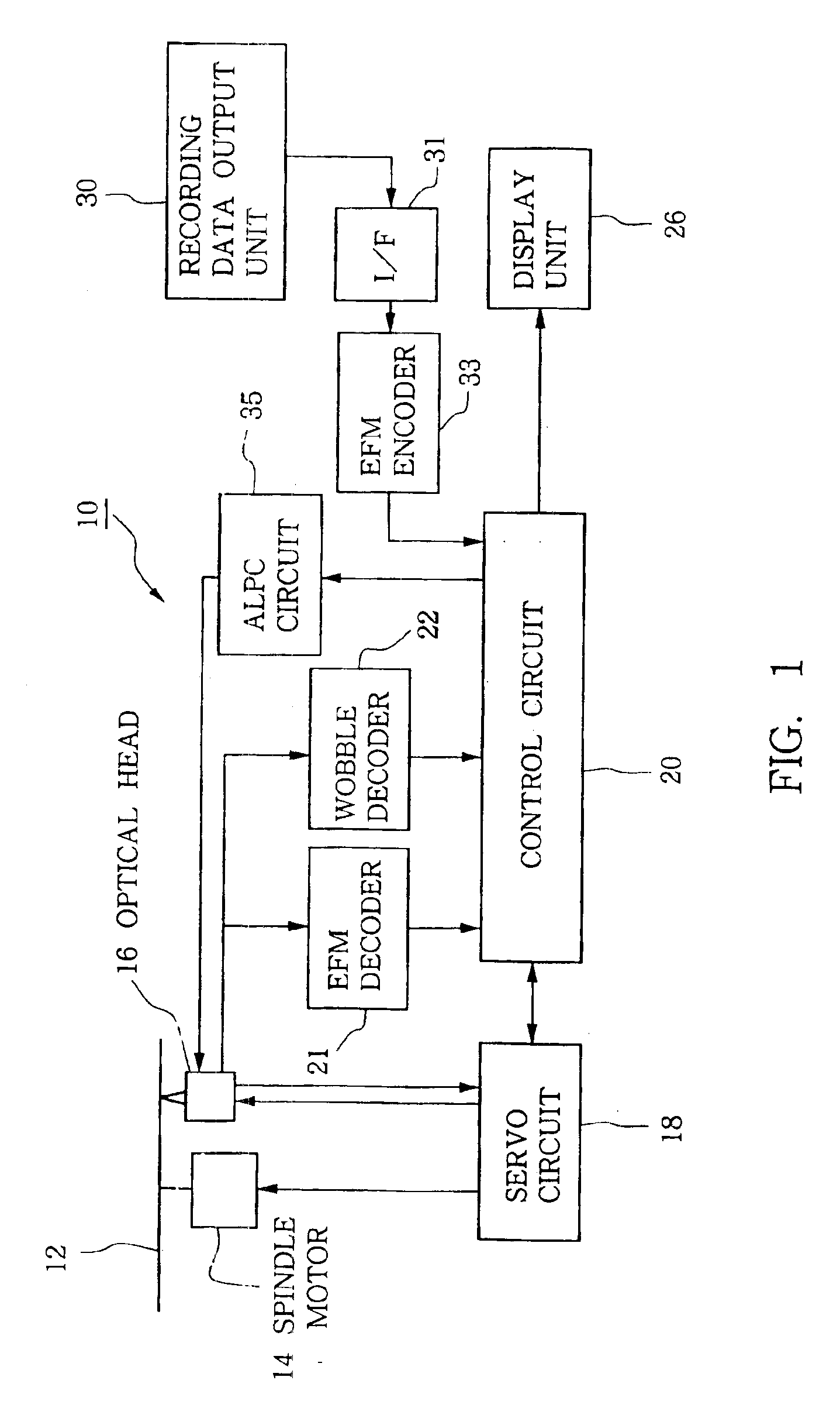
[0008]Further, the present invention provides an optical disk recording device for recording on an optical disk where disk-applicable-recording-speed information is incorporated in either one or both of lead-in start
time information and lead-out start
time information recorded in pre-groove wobbles or pre-pits of the optical disk, which comprises: a
time information reproducing circuit that reproduces, from among disk readout signals generated by reading the optical disk to be recorded on, either one or both of the lead-in start time information and the lead-out start time information recorded in the pre-groove wobbles or pre-pits of the optical disk; and a
control circuit that determines disk-applicable recording speeds on the basis of either one or both of the lead-in start time information and the lead-out start time information reproduced by the time information reproducing circuit and performs recording on the optical disk after setting a recording speed for the optical disk to a speed value within a range of the determined disk-applicable recording speeds. In this inventive optical disk recording device, recording can be performed on the recordable optical disk with the disk-applicable-recording-speed information incorporated in either one or both of the lead-in start time information and the lead-out start time information recorded in the pre-groove wobbles or pre-pits of the optical disk, using the recording speed set to a speed value within a range of the disk-applicable recording speeds indicated by the disk-applicable-recording-speed information. Thus, the recording can be executed with minimized errors. Note that in the case where the disk-applicable-recording-speed information is information indicative of an upper
limit value of the disk-applicable recording speeds and incorporated in either one or both of the lead-in start time information and the lead-out start time information recorded in the pre-groove wobbles or pre-pits of the optical disk, the
control circuit sets the recording speed for the optical disk to a value not exceeding the upper
limit value of the disk-applicable recording speeds.
[0009]The present invention further provides an optical disk recording device for recording on a recordable optical disk where one of lower and upper limit values of disk-applicable recording speeds is incorporated in lead-in start time information recorded in pre-groove wobbles or pre-pits of the optical disk and the other of the lower and upper limit values of the disk-applicable recording speeds is incorporated in lead-out start time information recorded in the pre-groove wobbles or pre-pits of the optical disk, which comprises a time information reproducing circuit that reproduces, from among disk readout signals generated by reading the optical disk to be recorded on, the lead-in start time information and the lead-out start time information recorded in the pre-groove wobbles or pre-pits of the optical disk; and a
control circuit that determines one of the lower and upper limit values of the disk-applicable recording speeds on the basis of the lead-in start time information reproduced by the time information reproducing circuit and the other of the lower and upper limit values of the disk-applicable recording speeds on the basis of the lead-out start time information reproduced by the time information reproducing circuit and performs recording on the optical disk after setting a recording speed for the optical disk to a speed value within a range of the
lower limit value to the upper
limit value of the disk-applicable recording speeds. In this inventive optical disk recording device, recording can be performed on the recordable optical disk with the recording speed set to a speed value within a range specified by the lower and upper limit values of the disk-applicable recording speeds. Thus, the recording can be executed with minimized errors.
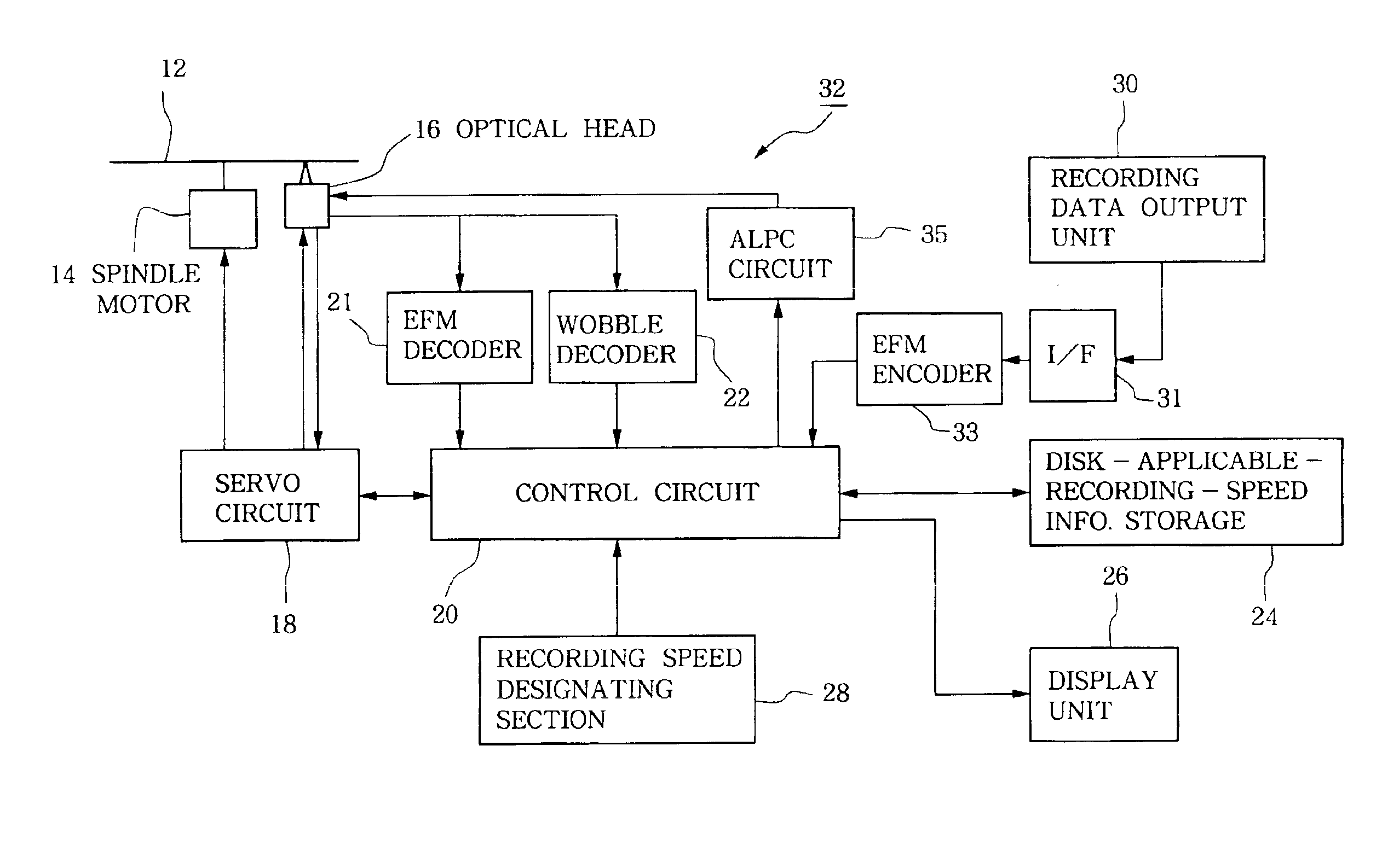
[0011]The present invention also provides an optical disk recording device which comprises: an disk-applicable-recording-speed information reproducing circuit that reproduces, from among disk readout signals generated by reading an optical disk to be recorded on, disk-applicable-recording-speed information pre-recorded on a track of the optical disk during manufacture of the optical disk; a display unit that displays disk-applicable recording speeds on the basis of the disk-applicable-recording-speed information reproduced by the disk-applicable-recording-speed information reproducing circuit; a recording speed designating section that designates a particular recording speed value on the basis of an operation by a user; and a control circuit that performs recording on the optical disk after setting a recording speed for the optical disk to the particular recording speed value designated by the recording speed designating section. With this inventive optical disk recording device, the user can set the recording speed to a speed value within the range of the displayed disk-applicable recording speeds by carrying out a manual input operation or the like while viewing the display on the display unit. Thus, the recording can be executed with minimized errors. Note that in the case where the disk-applicable-recording-speed information is recorded in the pre-groove wobbles or pre-pits of the optical disk, the disk-applicable-recording-speed information reproducing circuit reproduces the disk-applicable-recording-speed information from the pre-groove wobbles or pre-pits.


