Method to identify a key profile, machine to implement the method and apparatus for the duplication of keys utilizing the machine

a key profile and machine technology, applied in the field of methods for identifying key profiles, can solve the problems of false or incomplete reading, unfavorable operator safety, and risk of duplicating keys that cannot be inserted into the corresponding lock or cylinder,

Inactive Publication Date: 2005-05-17
SILCA SPA
View PDF11 Cites 77 Cited by
  • Summary
  • Abstract
  • Description
  • Claims
  • Application Information

AI Technical Summary

Problems solved by technology

Hence there is the problem of exactly identifying (reading) the profile of the blank key to be cut, this being a laborious operation for which a certain uncertainty exists, in that thousands of different key profiles are available commercially, sometimes differing by often imperceptible differences.
This is obviously a laborious operation with some uncertainty for the operator, and the risk of duplicating a key not able to be inserted into the corresponding lock or cylinder.
A further drawback is that even if the exact profile for the blank key to enable duplication has been correctly identified, there is always the problem of checking whether the cutting operation has been correctly carried out, this problem being particularly acute if the original key to be duplicated is considerably worn, in that the resultant key notching pattern does not reproduce the nominal pattern of the original key, but of the key as it currently appears, to which further tolerances have to be added deriving from the duplicating process.
A drawback of this solution is that the video camera determines only the key profile resulting from frontal observation, and as the video camera is focused on the end of the key shank, and hence views the profile as appearing at its end part, if at this end there exists notching which substantially reduces its profile, the reading is evidently false or incomplete, as is the subsequent comparative analysis effected by the control unit.
A further drawback of this solution is that although it is generally able to detect the profile of a key, it is however not able to detect its notching pattern and hence can neither compare the original key with the duplicated key to verify that it has been correctly cut, nor can it transfer its parameters to a duplicating machine.

Method used


Image

  • Method to identify a key profile, machine to implement the method and apparatus for the duplication of keys utilizing the machine
  • Method to identify a key profile, machine to implement the method and apparatus for the duplication of keys utilizing the machine
  • Method to identify a key profile, machine to implement the method and apparatus for the duplication of keys utilizing the machine

Examples


Embodiment Construction

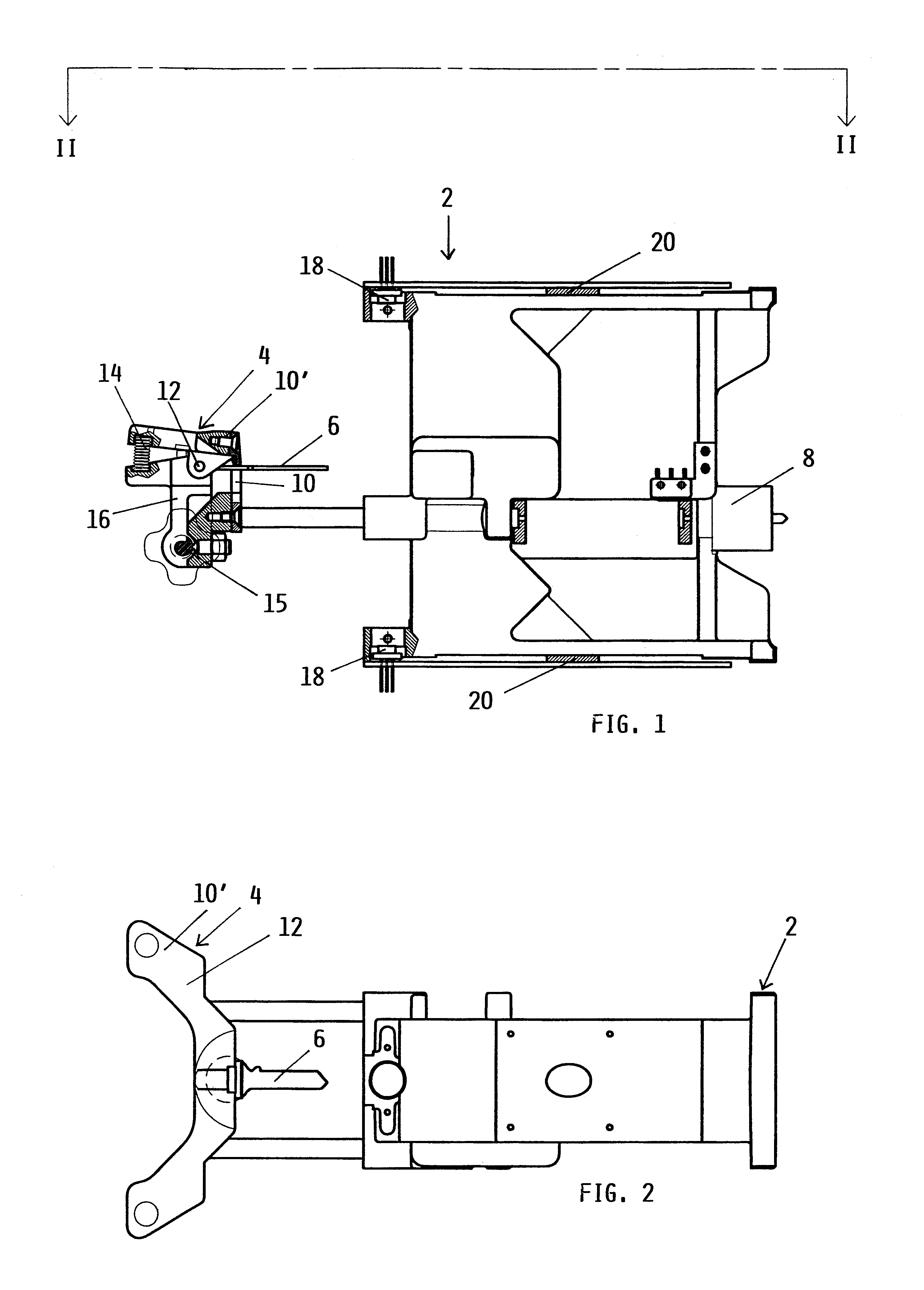
[0026]As can be seen from the figures, the method of the invention uses a machine comprising a base frame, indicated overall by 2, on which there is mounted a clamp 4 for a key 6, the profile of which is to be determined. The clamp 4 is mounted on a traditional linear actuator 8 able to move it in both directions parallel to the longitudinal axis of the key 6 retained by said clamp.

[0027]The clamp 4 comprises a pair of jaws 10, 10′, one of which 10 is fixed to the linear actuator 8 and the other 10′ is hinged to the first on a pair of coaxial horizontal pins 12.

[0028]Two springs 14 are interposed between the two jaws 10, 10′ to maintain the jaws in their closed configuration.

[0029]To prevent these springs yielding to cause unintentional opening of the clamp 4 in certain circumstances, for example if the key for which the profile is to be determined forms part of a bunch of keys, the weight of which could open said clamp, a device comprising a cam 15 and rod 16 is provided to lock th...


PUM

PropertyMeasurementUnit
optical imagesaaaaaaaaaa
optical imageaaaaaaaaaa
weightaaaaaaaaaa

Abstract

A method to identify a key profile, comprising:
  • illuminating with two laminar beams emitted by two laser light sources said two sides of said shank of a key driven to move axially relative to said beams,
  • reading with two video cameras, fixed relative to said sources and having their optical axis inclined to said planes in which said light beams lie, said two light profiles formed by said laminar beams striking said two surfaces of said shank of said keys,
  • digitizing said optical images read in this manner, to obtain two sequences of signals representative of said profiles of said two lateral surface portions of said key, as instantaneously illuminated by said laminar beams and read by said video cameras,
  • reconstructing from said signals, by means of a processor unit, a signal representative of the entire key profile, and
  • comparing said thus reconstructed signal with said signal representative of profiles stored in said processor unit to obtain data identifying said profile of said read key.

Description

[0006]This application is the national phase under 35 U.S.C. § 371 of PCT International Application No. PCT / EP00 / 01792 which has an International filing date of Feb. 1, 2000, which designated the United States of America and was published in English.FIELD OF INVENTION[0007]This invention relates to a method to identify a key profile, a machine to implement the method and an apparatus for the duplication of keys utilizing the machine.DESCRIPTION FOR THE PRIOR ART[0008]Keys for locks or cylinders are known comprising a head of the most varied shapes and a shank having a profile compatible with the lock or cylinder associated with said key and suitable for receiving a series of notches which overall form the key notching pattern, ie its personalization for operating that particular lock or cylinder.[0009]If it is required to form an additional key able to operate a given lock or cylinder, a blank key, ie having the profile corresponding to that lock or cylinder but without the notching...

Claims


Application Information

Patent Timeline
Patent Type & Authority Patents(United States)
IPC IPC(8): B23C3/35B23C3/00G06K9/00G06V20/66
CPCB23C3/35G06K9/00Y10T409/300952E05B19/0011G06V20/66G06F18/00
Inventor PACENZIA, STEFANOCASAGRANDE, ETTOREFOSCAN, EROS
Owner SILCA SPA
Why Eureka
Try Eureka