Method and apparatus for data relocation between storage subsystems

a technology of storage subsystems and methods, applied in the field of computer systems, can solve the problems of data not being able to be relocated between different storage subsystems, the amount of information is so vast, and it is difficult for a host computer to externally access the storage subsystem

Inactive Publication Date: 2005-05-17
HITACHI LTD
View PDF10 Cites 75 Cited by
  • Summary
  • Abstract
  • Description
  • Claims
  • Application Information

AI Technical Summary

Benefits of technology

[0024]According to this invention, a vast amount of information including the performance information and the utilization rate history collected and stored in each storage subsystem are not required to be collected or managed in other than the storage subsystems (such as a host computer or a virtualization device), and the data can be relocated in and between the storage subsystems. Specifically, only in the case where the data are

Problems solved by technology

In a computer system having a plurality of storage subsystems, however, data cannot be relocated between different storage subsystems.
The amount of these information is so vast that it is difficult for a host computer external to the storage subsystems, for example, to collect these in

Method used


Image

  • Method and apparatus for data relocation between storage subsystems
  • Method and apparatus for data relocation between storage subsystems
  • Method and apparatus for data relocation between storage subsystems

Examples


Embodiment Construction

[0046]An embodiment of the invention will be explained below with reference to the accompanying drawings. In the description below, the component parts having the same functions will be designated by the same reference numerals, respectively, and will not be explained again.

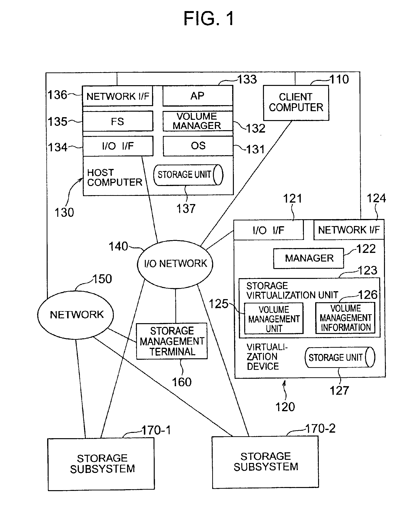
[0047]FIG. 1 is a diagram showing a configuration of a computer system according to this embodiment. This system is configured of a host computer 130, a client computer 110, a plurality of storage subsystems 170, a virtualization device 120, a storage management terminal 160, an I / O network 140 for interconnecting the units and a network 150 for interconnecting the units.

[0048]The host computer 130 has mounted thereon an operating system (OS) 131, a filing system (FS) 135, a volume manager 132 and an application program (AP) 133, and is executed by a processor unit thereof. The volume manager 132 is a program for managing the volume handled by the host computer 130. The host computer 130 includes a storage unit 1...


PUM


Abstract

A storage subsystem that has detected the necessity of the data relocation determines whether the data relocation is possible or not from one storage unit to another within the particular storage subsystem. A virtualization device is notified in the case where the data relocation in the particular subsystem is impossible. The manager of the virtualization device gives an inquiry to the storage subsystems as to whether any one of them can become a relocation destination or not. A storage subsystem determines, based on the related information, whether the data relocation requested is possible or not within the particular storage subsystem. In the case where such a relocation is possible, the copying process is carried out for data relocation from one storage subsystem to another in compliance with an instruction from the virtualization device.

Description

BACKGROUND OF THE INVENTION[0001]1. Field of the Invention[0002]The present invention relates to a computer system having a plurality of storage subsystems, or in particular to a technique for relocating data from one storage subsystem to another.[0003]2. Description of the Related Art[0004]In a computer system, one of the secondary storage systems for realizing a high performance is a disk array system. The disk array system has a plurality of physical storage units arranged in an array, and the read / write operation of data stored distributively in the physical storage units are performed in parallel to achieve a high-performance storage.[0005]An article on the disk array system is D. A. Patterson, G. Gibson, and R. H. Kats, “A Case for Redundant Arrays of Inexpensive Disks” (in Proc. ACM SIGMOD, pp. 109-116, June 1988). This article deals with a disk array system having a redundancy divided into five types of levels 1 to 5 according to the configuration thereof. In addition to the...

Claims


Application Information

Patent Timeline
IPC IPC(8): G06F12/00G06F3/06G06F12/16
CPCG06F3/0605G06F3/0631G06F3/067G06F3/0653G06F3/0649
Inventor EGUCHI, YOSHIAKIARAKAWA, HIROSHIYAMAMOTO, YASUTOMOIWAMURA, TAKASHIGEARAI, KOUJI
Owner HITACHI LTD
Why Eureka
Try Eureka