Supercharge Your Innovation With Domain-Expert AI Agents!

System and method for generating cyclic codes for error control in digital communications

Inactive Publication Date: 2005-05-17
AVAGO TECH WIRELESS IP SINGAPORE PTE
View PDF3 Cites 7 Cited by
  • Summary
  • Abstract
  • Description
  • Claims
  • Application Information

AI Technical Summary

Benefits of technology

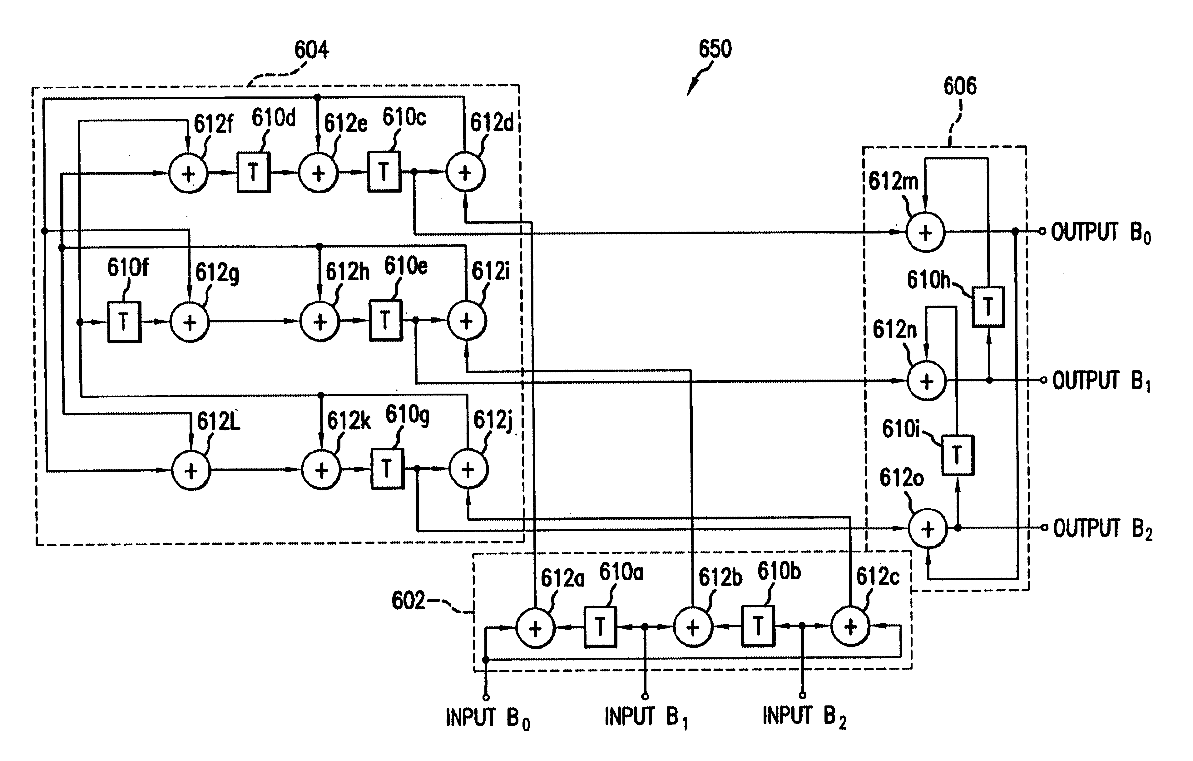
[0010]Systems and methods for generating cyclic codes for error control in digital communications are presented. Generally speaking, the invention operates by receiving an initial group of information bits to be transmitted. This initial group of information bits is oper

Problems solved by technology

These conventional systems and methods, however, have limitations that prevent them from operating at high data rates.
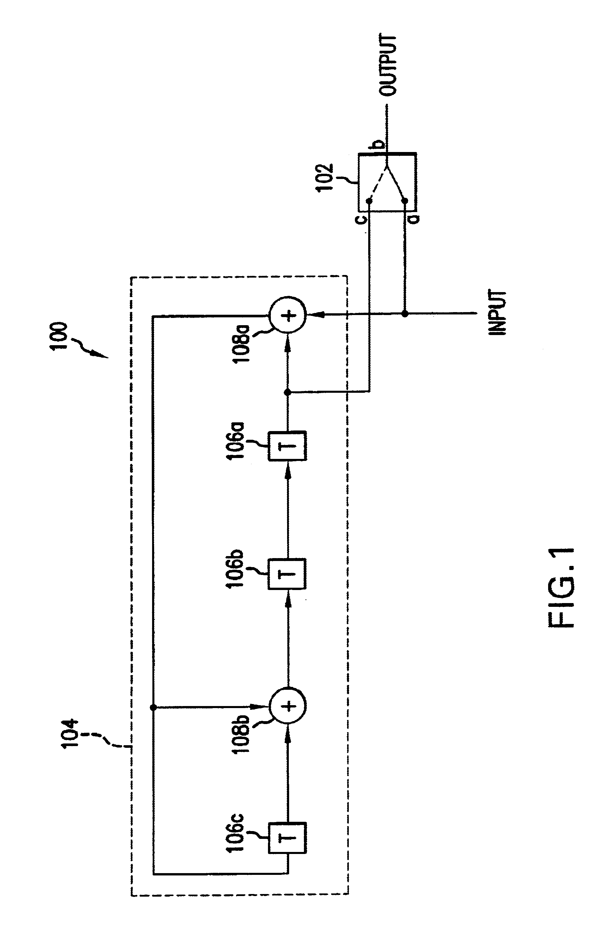
In particular, the nested feedback loops of the LFSR used to generate the code words form a speed bottleneck.
These conventional techniques, however, cannot always be applied successfully to design digital communications systems that will operate at a data rate in excess of 2 Gb / s.
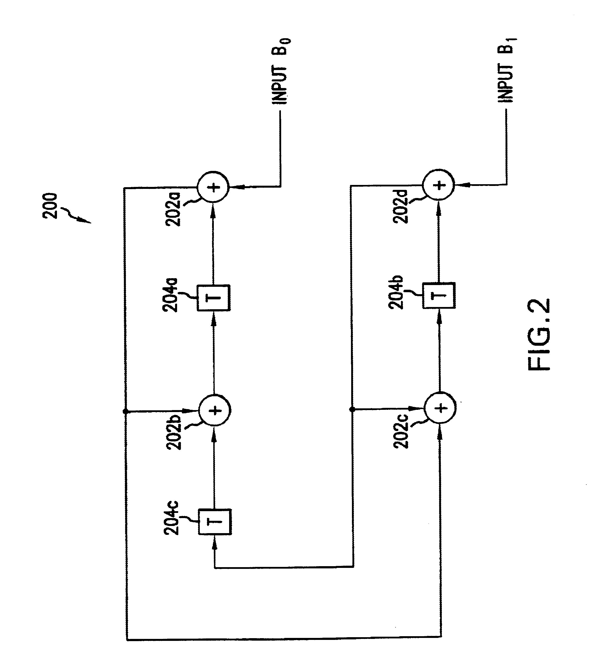
Applying these conventional techniques is particularly difficult, for example, when dealing with nested feedback loops such as the feedback loops of a linear feedback shift register used to generate the code words of a cyclic code.
Many of these approaches will not, however, improve the performance of the digital circuit to which they are applied, and some of these approaches can even degrade circuit performance or improve the performance in a less-than-linear manner with respect to look-ahead factor.
In similar fashion, the application of conventional pipelining and parallelism techniques to nested feedback loops in high speed digital communications systems will not necessarily result in improved performance.
Applying these conventional techniques leads to fan-out problems in a high speed digital communications system, and thus they cannot be used to overcome speed bottlenecks caused by nested feedback loops in a high speed digital communications system.

Method used


Image

  • System and method for generating cyclic codes for error control in digital communications
  • System and method for generating cyclic codes for error control in digital communications
  • System and method for generating cyclic codes for error control in digital communications

Examples


example method

for Generating Cyclic Codes According to the Invention

[0079]In this section, an example method for generating cyclic codes according to the invention is described. This method can be implemented using the techniques and circuit embodiments of the invention described above. The example method is not limited, however, to being implemented using only the circuits described herein.

[0080]FIG. 11 is a flowchart of the steps of a method 100 for generating cyclic codes for error control in digital communications. In the example of FIG. 11, method 1100 includes four steps 1102, 1104, 1106, and 1108. Method 1100 starts with step 1102.

[0081]In step 1102, a K-bit information signal is received. This information signal is represented by a polynomial U(x) having a degree K−1.

[0082]In step 1104, the information signal U(x) is transformed to form a transformed information signal. The information signal U(x) is transformed using a first transform represented by a polynomial G1(x) having a degree P. ...


PUM


Abstract

A K-bit information signal represented by a polynomial U(x) having a degree K−1 is received. The information signal is transformed to form a transformed information signal using a first transform represented by a polynomial G1(x) having a degree P. The transformed information signal is represented by a polynomial T(x) having a degree K+P−1. T(x) equals U(x)G1(x). An initial cyclic code represented by a polynomial R1(x) is generated for the transformed information signal using a second transform represented by a polynomial G2(x), where G2(x) has high-order leading-zero terms. R1(x) equals the remainder obtained by dividing T(x) by G2(x). The initial cyclic code is transformed to form a final cyclic code represented by a polynomial R2(x) using the first transform. R2(x) equals R1(x) / G1(x).

Description

CROSS REFERENCE TO RELATED APPLICATIONS[0001]This application is a continuation-in-part of U.S. application Ser. No. 10 / 055,910, filed Jan. 28, 2002, which in incorporated by reference herein in its entirety.FIELD OF THE INVENTION[0002]The present invention relates to digital communications. More particularly, the present invention relates to cyclic codes for error control in digital communications.BACKGROUND OF THE INVENTION[0003]Communicating information via the internet and other digital communications systems has become common in the United States and elsewhere. As the number of people using these communications systems has increased, so has the need for transmitting digital data at ever increasing rates.[0004]Information transmitted by a digital communications system is typically encoded and transmitted as a series of information code words. Encoding is used to improve the overall performance of a digital communications system. In addition to encoding information prior to trans...

Claims


Application Information

Patent Timeline
IPC IPC(8): H04J3/04H04L25/03H03M13/09H03M13/15
CPCH03M13/091H03M13/15H04L25/03057H04J3/047H03M13/617
Inventor PARHI, KESHAB K.
Owner AVAGO TECH WIRELESS IP SINGAPORE PTE
Features
  • R&D
  • Intellectual Property
  • Life Sciences
  • Materials
  • Tech Scout
  • Unparalleled Data Quality
  • Higher Quality Content
  • 60% Fewer Hallucinations
Learn More