Common rail type fuel injection system

Active Publication Date: 2005-05-24
DENSO CORP
View PDF10 Cites 28 Cited by
  • Summary
  • Abstract
  • Description
  • Claims
  • Application Information

AI Technical Summary

Benefits of technology

[0007]The present invention has been made in view of the above-mentioned problem, and an object of the present invention is to provi

Problems solved by technology

There has been the following problem in such a conventional system.
When a large amount of air is sucked at a time into the feed

Method used


Image

  • Common rail type fuel injection system
  • Common rail type fuel injection system
  • Common rail type fuel injection system

Examples


Embodiment Construction

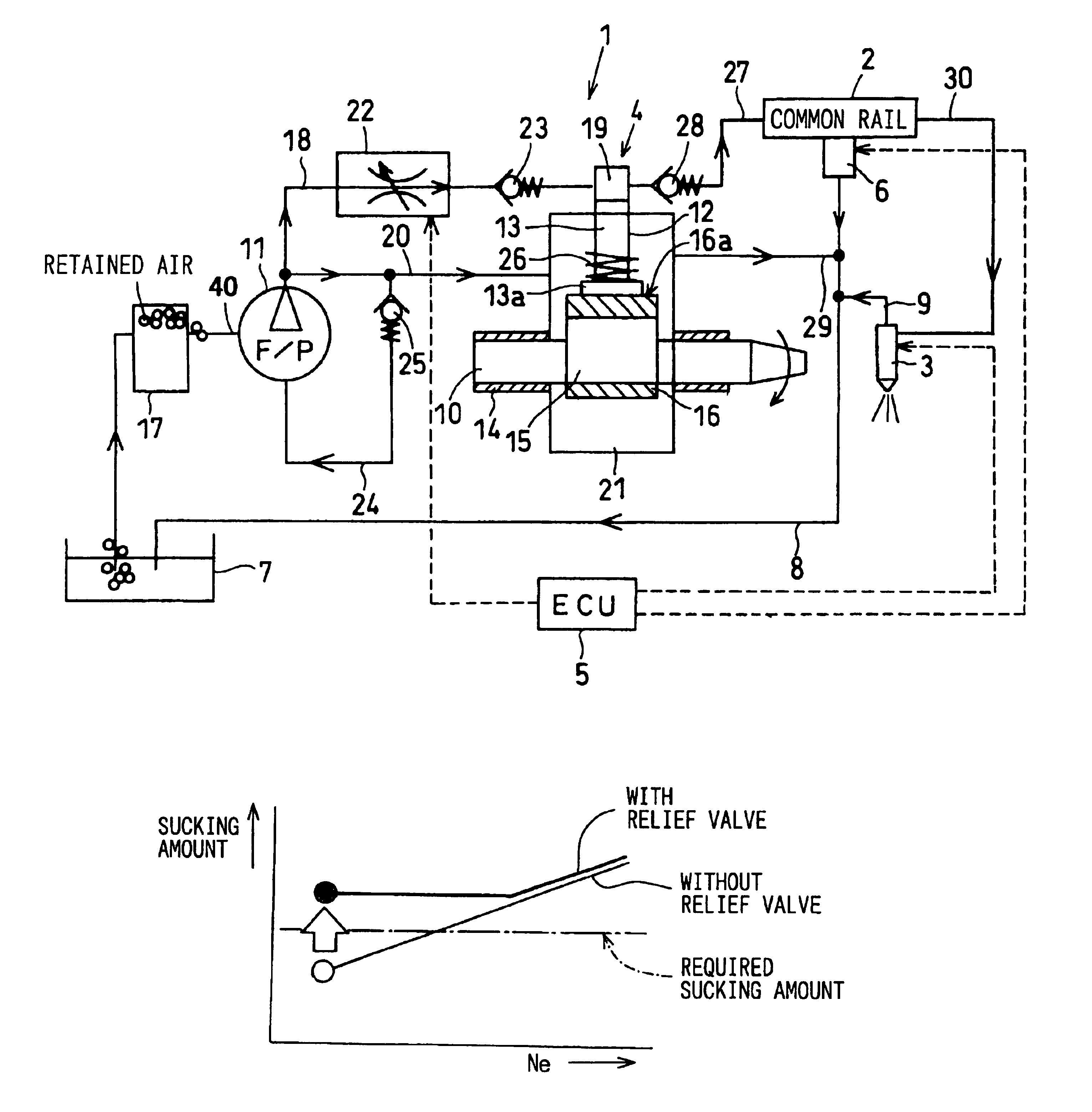
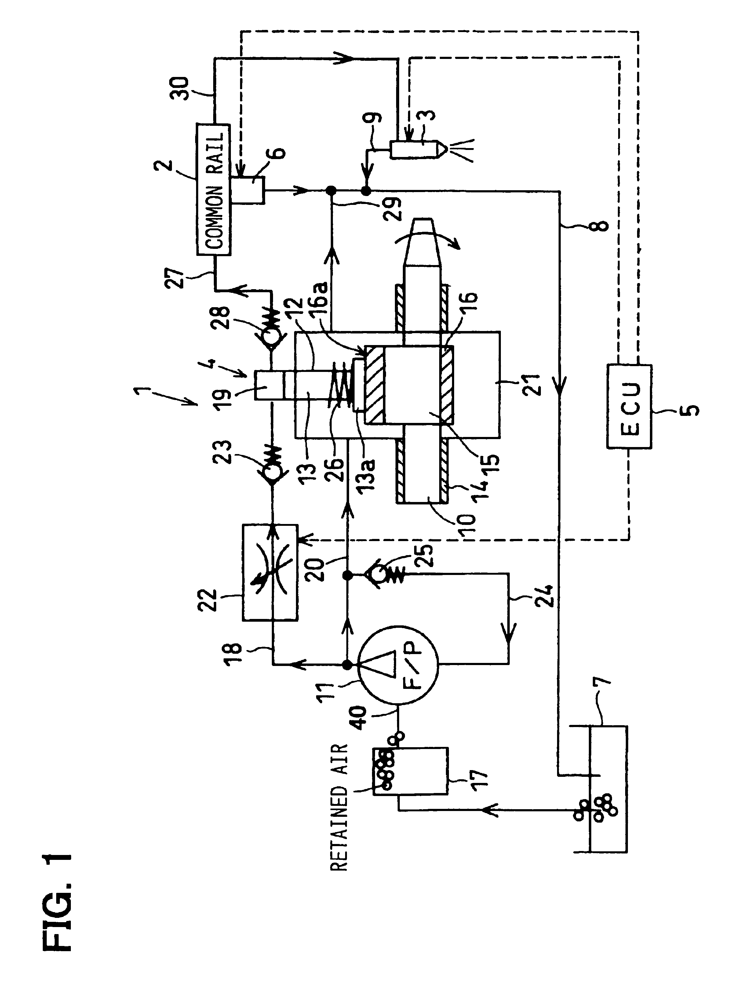
[0015]A preferred embodiment of the present invention will be described with reference to accompanying drawings. First, referring to FIG. 1, an entire structure of a common rail type injection system 1 of the present invention will be described. The fuel injection system 1 is applied to a diesel engine mounted on an automobile vehicle, for example. The system includes a common rail 2 in which pressurized fuel is stored; an injector 3 that injects the pressurized fuel supplied from the common rail 2 into a cylinder of an engine; a fuel supply pump 4 for supplying the pressurized fuel to the common rail 2; an electronic control unit (ECU) 5 for electronically control operation of the system; and other associated components.

[0016]The common rail 2 stores fuel pressurized at a target pressure (a target rail pressure) calculated based on a rotational speed Ne of the engine and an engine load Le (corresponding to an opening degree of an accelerator). The common rail 2 is connected through...


PUM


Abstract

In a common rail type fuel injection system, fuel in a fuel tank is sucked by a feed pump and fed to a pressurizing pump. Fuel pressurized in the pressurizing pump is supplied to a common rail. The pressurized fuel accumulated in the common rail is injected into a cylinder of an internal combustion engine from an injector. All of these operations are electronically controlled by an electronic control unit. To gradually suck air in the fuel tank together with fuel and to avoid air accumulation in a fuel filter, a relief valve is connected to the common rail. The relief valve is opened when the engine is idling thereby to increase an amount of fuel sucked by the feed pump and to gradually suck the air together with the fuel. The relief valve is opened only in interval periods in which fuel is not injected from the injector.

Description

CROSS-REFERENCE TO RELATED APPLICATIONS[0001]This application is based upon and claims benefit of priority of Japanese Patent Applications No. 2003-185751 filed on Jun. 27, 2003 and No. 2004-127997 filled on Apr. 23, 2004, the contents of which are incorporated herein by reference.BACKGROUND OF THE INVENTION[0002]1. Field of the Invention[0003]The present invention relates to a common rail type fuel injection system for supplying pressurized fuel into an internal combustion engine such as a diesel engine.[0004]2. Description of Related Art[0005]An example of this type of a fuel injection system is disclosed in JP-A-2001-295685. In this system, fuel in a fuel tank is sucked by a feed pump and fed to a fuel supply pump that pressurizes the fuel. The pressurized fuel is supplied to a common rail that accumulates therein the pressurized fuel. The pressurized fuel is injected from an injector into a cylinder of a diesel engine. Injection timing and amount of fuel injected into the cylind...

Claims


Application Information

Patent Timeline
IPC IPC(8): F02M63/02F02M59/00F02M59/46F02M63/00F02D41/08F02M37/00F02M37/20F02M47/00F02M51/00F02M55/00
CPCF02M63/025F02M63/0225F02M59/466F02D41/08
Inventor KURODA, AKIHIRO
Owner DENSO CORP
Why Eureka
Try Eureka