
Equipoise arm assembly

a technology of equipoise and arm, which is applied in the direction of machine supports, lighting and heating apparatus, and support devices for supporting devices, etc., can solve the problems of difficulty in accommodating the changing moment arm, the resistive force required to retain it in equipoise condition, and the inability to achieve such an ideal-performing mechanical arm arrangemen

Inactive Publication Date: 2005-05-24
CVEK SAVA
View PDF18 Cites 77 Cited by
  • Summary
  • Abstract
  • Description
  • Claims
  • Application Information

AI Technical Summary

Benefits of technology

[0010]A related object of particular embodiments of the invention is to provide a mechanical equipoise arm assembly that can provide resistive support corresponding to nonlinear changes in the moment arm presented by an arm or arms.
[0011]Yet another object of certain embodiments of the invention is to provide an equipoise arm assembly that can be moved between equipoise positions with the application of a very slight force.
[0013]An even further object of the invention is to provide an equipoise arm assembly that can retain electrical wiring generally shielded from external view and from damage.
[0014]Even further still, an object of certain embodiments of the invention is to provide an equipoise arm assembly that is not likely to pinch or crush an operator's body parts or other surrounding elements.
[0019]In any case, a parallelogram pivoting arrangement can be established between the support arm and the proximal and distal arm joints such that the distal arm joint will demonstrate parallel movement relative to the proximal arm joint. That parallelogram pivoting arrangement can be provided by first and second control arms each with a proximal end pivotally coupled to the proximal arm joint and a distal end pivotally coupled to the distal arm joint. Where at least a first control arm forms part of the parallelogram pivoting arrangement, the distal end of the spring arrangement can be coupled to the first control arm. The spring arrangement in certain cases can include a plurality of spaced coupling points for the spring member such that it can have any one of a variety of initial spring extensions. Under such a construction, the spring arrangement can be readily adapted to provide support to articles of differing weights.

Problems solved by technology

For a plurality of reasons, however, the creation of such an ideally performing mechanical arm arrangement has proven elusive.
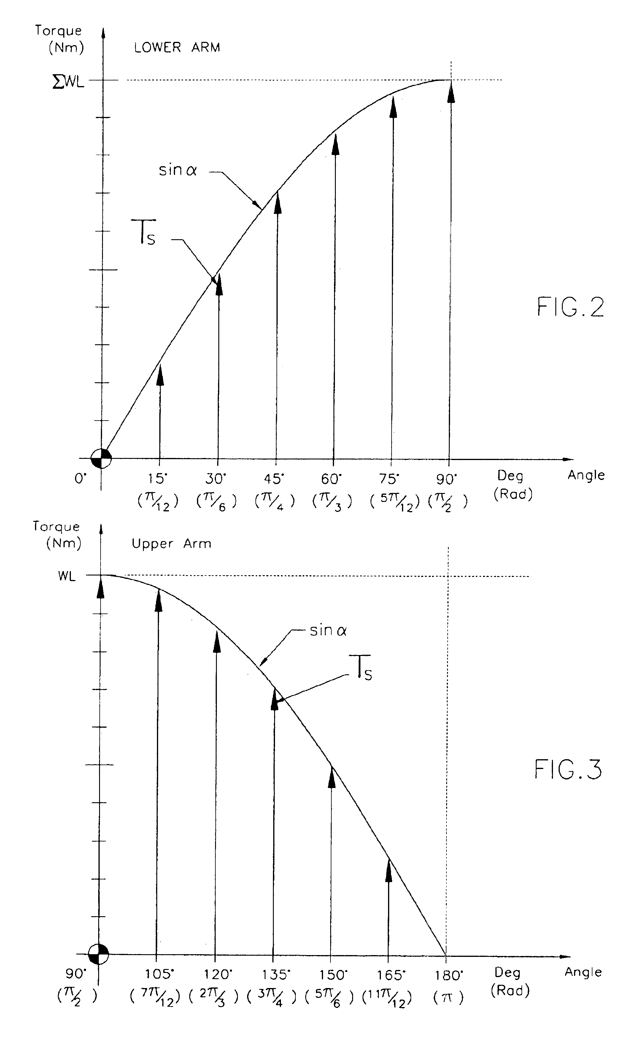
One fundamental challenge that has confronted inventors of the prior art derives from the fact that, as the angle of a support arm changes relative to vertical, the resistive force required to retain it in an equipoise condition will necessarily vary as well.
Accommodating that changing moment arm is rendered particularly difficult in a mechanical arm arrangement since it varies over a nonlinear sine curve as the angular disposition of the support arm is progressively increased or decreased.
Consequently, even when a spring arrangement has been specifically designed to support a given weight, the spring or springs will tend to provide excessive resistance over one or more portions of the arm's range of motion while providing too little resistance over one or more other portions of the arm's range of motion.
With this, although highly desirable, crafting an arm arrangement capable of supporting an article in a state of equipoise over a broad range of arm angles has been notably difficult.
A plurality of additional issues and considerations further complicate the design and manufacture of equipoise support arms.
However, it will be appreciated that such a practice leads to a plurality of complications.
A further design issue derives from the fact that electrical power often must be provided to the supported article such that wiring must normally traverse the support arm or arms thereby harming the aesthetics of the arm construction and possibly interfering with the function of the arm or arms.
Even further, in many prior art arrangements, each arm is founded on a parallelogram formed by multiple exposed bars that can pinch and otherwise pose a potential danger to the user.

Method used


Image

  • Equipoise arm assembly
  • Equipoise arm assembly
  • Equipoise arm assembly

Examples


Embodiment Construction

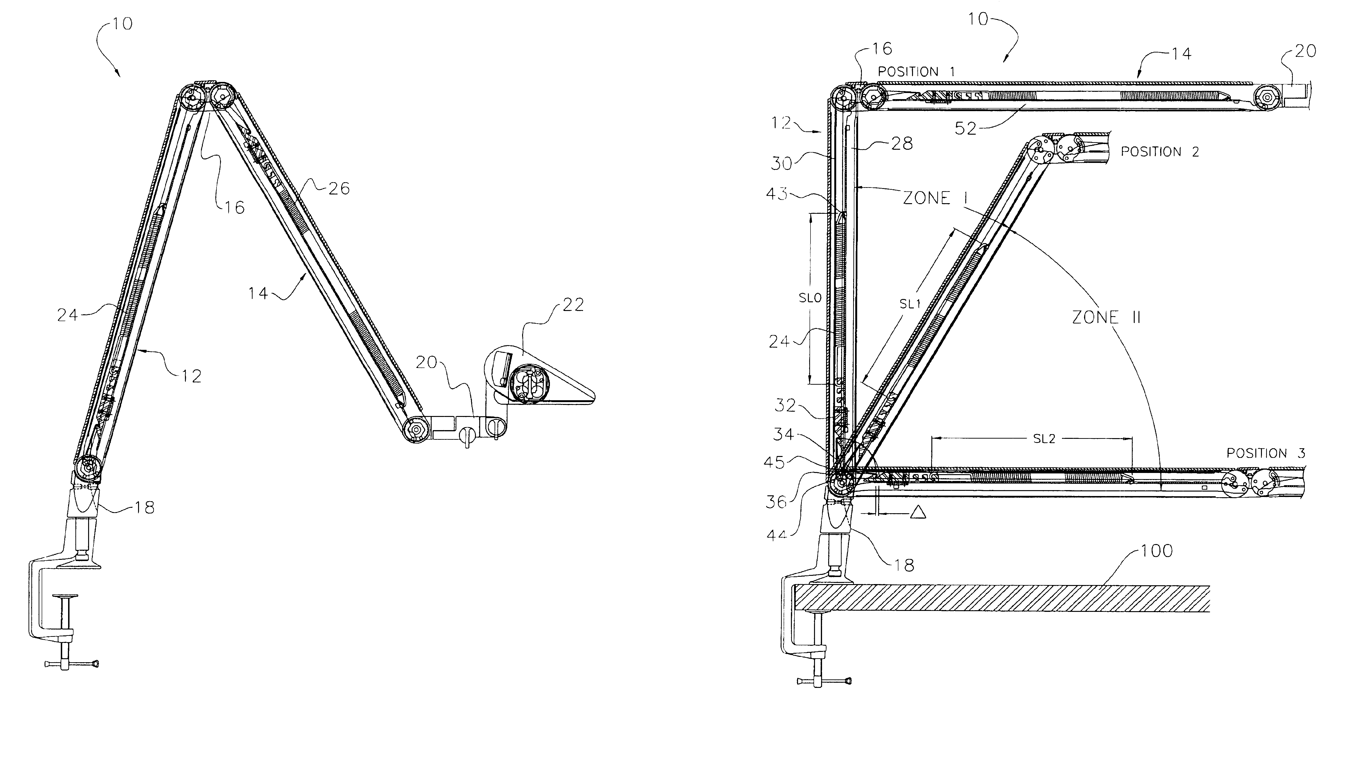
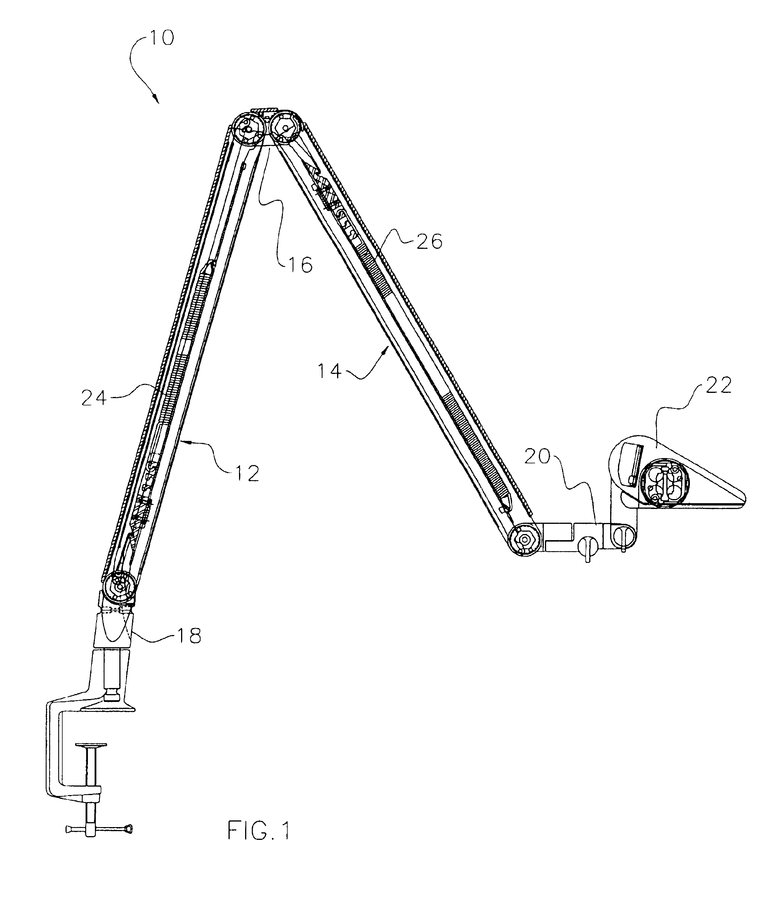
[0040]As with many inventions, the present invention for an equipoise arm assembly can assume a wide variety of embodiments. However, to assist those reviewing the present disclosure in understanding and, in appropriate circumstances, practicing the present invention, certain exemplary embodiments of the equipoise arm assembly are described below and shown in the accompanying drawing figures.

[0041]Looking more particularly to the drawings, an exemplary equipoise arm assembly is indicated generally at 10 in FIG. 1. There, the exemplary equipoise arm assembly 10 is founded on a first, lower support arm 12 that is joined to a second, upper support arm 14 by a middle joint 16. More particularly, the lower support arm 12 has a proximal end retained by a lower arm joint 18 that supports the equipoise arm assembly 10 relative to a support structure (not shown) and a distal end coupled to the middle joint 16. The upper support arm 14 has a proximal end coupled to the middle joint 16 and a d...


PUM


Abstract

An equipoise arm assembly for supporting an article in equipoise with a support arm, a proximal arm joint, a distal arm joint for supporting an article either directly or through a second support arm, a spring arrangement including a spring member with a distal end coupled to a body portion of the support arm and a proximal end pivotally retained to pivot about an effective pivot axis to create a spring force moment arm of a given length whereby the spring arrangement will tend to provide a resistive torque in support to the support arm, and an arrangement for altering the effective pivot axis of the spring arrangement to change the length of the spring force moment arm.

Description

FIELD OF THE INVENTION[0001]The present invention relates generally to support structures. Stated more particularly, this patent discloses and protects an arm assembly for supporting an article in a state of equilibrium and demonstrating obedient movement in the support of that article.BACKGROUND OF THE INVENTION[0002]There are, of course, numerous applications where movable arms are employed for supporting one or more articles. By way of example, a multitude of structures has been disclosed for use in home, office, medical, and other applications wherein a lamp is supported by one or more articulated arms. Other articulated arm arrangements have been disclosed for supporting magnifying arrangements of various sizes, weights, and configurations. Still other arm arrangements have been particularly designed for providing adjustable support to computer monitors and similar articles.[0003]In these and further articulated arm structures, a most fundamental goal is to support the retained...

Claims


Application Information

Patent Timeline
IPC IPC(8): F16M13/02F16M11/04F16M11/02F21V21/14F21V21/26
CPCF16M11/04F16M11/10F16M11/2064F16M11/2092F16M11/24F21V21/26F16M13/022F16M13/02F16M2200/024F16M2200/044F16M2200/063F21V21/088
Inventor CVEK, SAVA
Owner CVEK SAVA
Learn More