High-load capability non-explosive cable release mechanism

a non-explosive, high-load technology, applied in the direction of transportation and packaging, aircrafts, cosmonautic vehicles, etc., can solve problems such as mechanical actuation

Active Publication Date: 2005-05-24
G&H TECH INC
View PDF14 Cites 9 Cited by
  • Summary
  • Abstract
  • Description
  • Claims
  • Application Information

AI Technical Summary

Benefits of technology

[0035]The present invention is a lightweight, redundant, non

Problems solved by technology

This in turn allows spring-loaded plungers to drive t

Method used


Image

  • High-load capability non-explosive cable release mechanism
  • High-load capability non-explosive cable release mechanism
  • High-load capability non-explosive cable release mechanism

Examples


Embodiment Construction

[0049]Although specific embodiments of the present invention will now be described with reference to the drawings, it should be understood that such embodiments are by way of example only and merely illustrative of but a small number of the many possible specific embodiments which can represent applications of the principles of the present invention. Various changes and modifications obvious to one skilled in the art to which the present invention pertains are deemed to be within the spirit, scope and contemplation of the present invention as further defined in the appended claims.

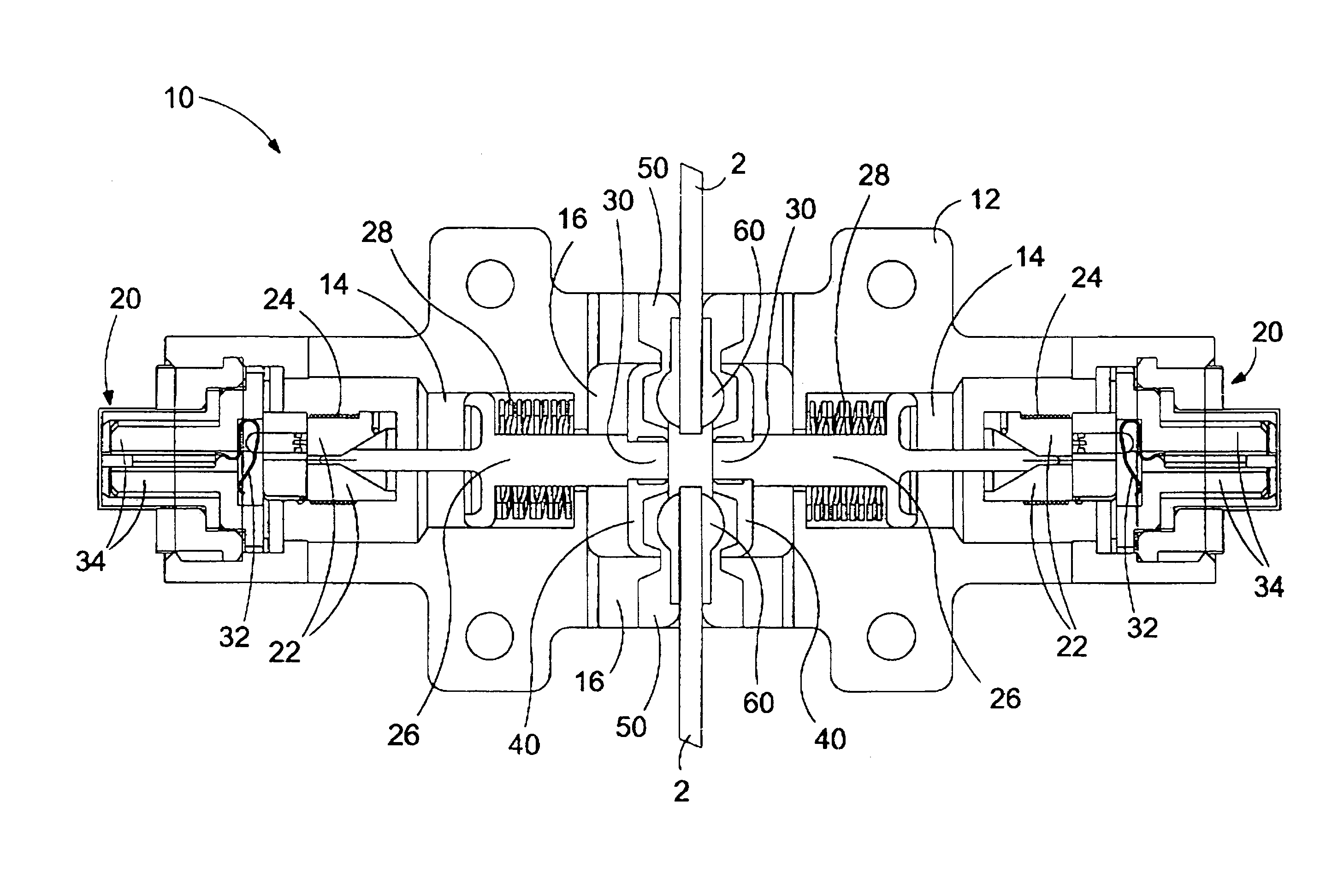
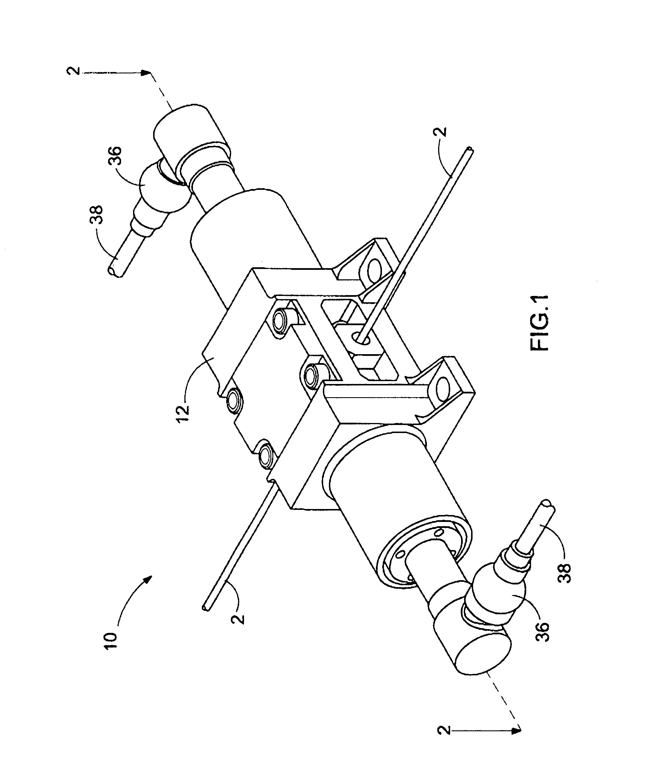
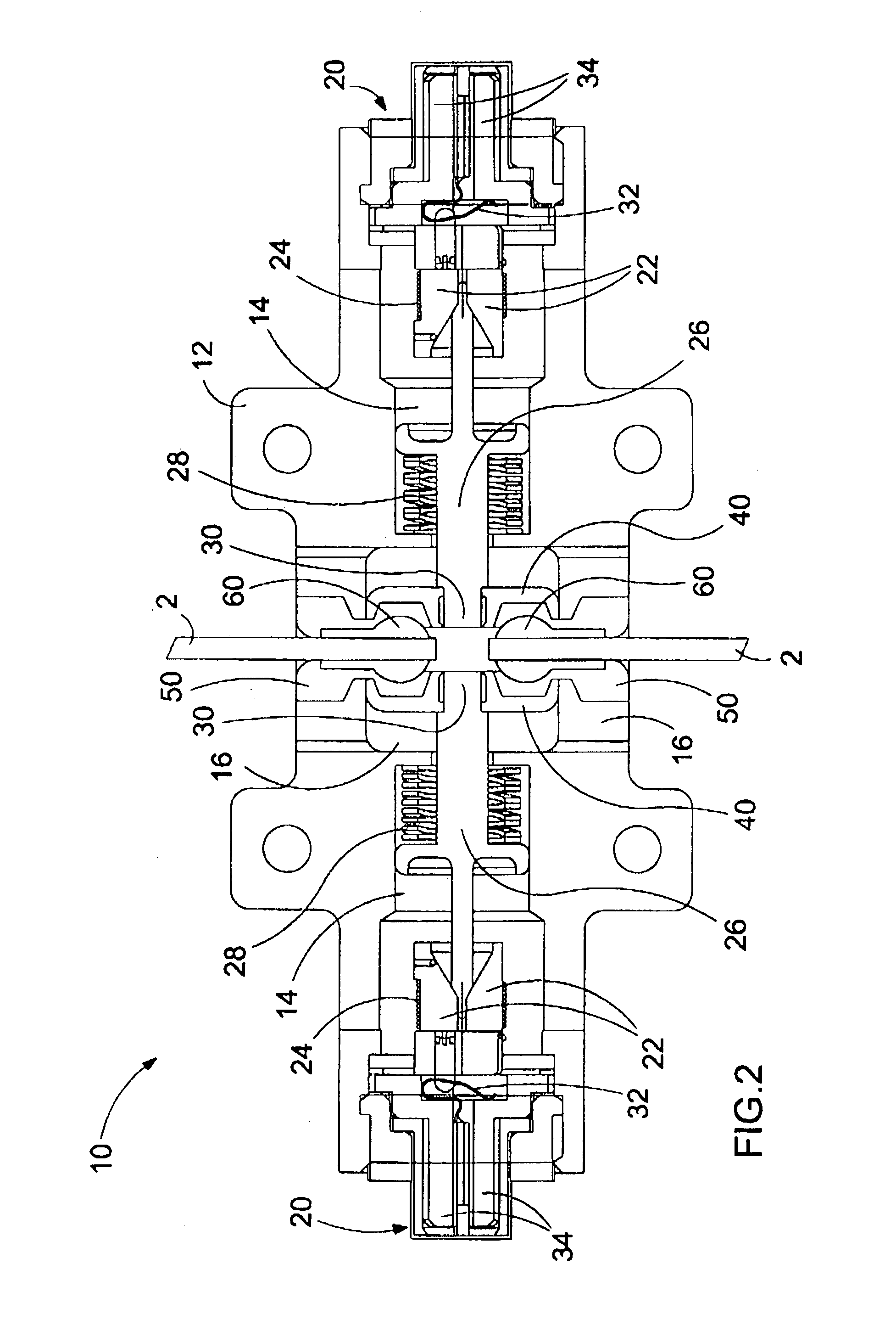
[0050]Referring to FIGS. 1 and 2, there is shown at 10 one of the preferred embodiments of the present invention high-load capability non-explosive cable release mechanism used in mechanical structural separation applications. The purpose of the cable release mechanism 10 is to hold the adjacent ends of two cables 2 together when required, and release them in a non-explosive manner when needed.

[0051]The hi...


PUM


Abstract

A high-load capability non-explosive cable release mechanism for retaining the adjacent ends of two cables and releasing them upon receiving a signal from a remote source. The cable release mechanism has a casing for housing two non-explosive actuators (NEAs), which also has a center bore for housing a jaw and ramp assembly. Each NEA is connected to the jaw and ramp assembly for independently operating the jaw and ramp assembly to retain or release the proximal ends of the two cables. Upon receiving the signal by any one or both of the NEAs, the jaw and ramp assembly will release the adjacent ends of the two cables from the casing.

Description

BACKGROUND OF THE INVENTION[0001]1. Field of the Invention[0002]The present invention generally relates to the field of mechanical structural separation devices used in aerospace, manufacturing and construction industries, and more particularly relates to the structure and designs of non-explosive cable release mechanisms.[0003]2. Description of the Prior Art[0004]Cable release mechanism are often utilized in aerospace, manufacturing and construction industries. One example of utilizing such mechanisms is to provide a quick and reliable release of the joined ends of two cables for component deployment of spacecraft. Preferably, the release mechanism is designed to be used in a repeatable manner.[0005]The following (15) prior art patents are found to be pertinent to the field of the present invention:[0006]1. U.S. Pat. No. 2,489,984 issued to Shoemaker on Nov. 29, 1949 for “Explosive-Release Mechanism” (hereafter the “Shoemaker Patent”); [0007]2. U.S. Pat. No. 3,012,811 issued to San...

Claims


Application Information

Patent Timeline
IPC IPC(8): B66C1/28B66C1/22B64G1/64
CPCB64G1/645Y10S294/905
Inventor WU, JUI-YULAUGHLIN, PATRICK
Owner G&H TECH INC
Why Eureka
Try Eureka